


View Camera History and Technology Series No. 1
To Turn a Camera
A Survey of Camera Designs
to Enable a Horizontal or Vertical Photograph Format
From photography’s beginnings, photograph dimensions have generally been rectangular, e.g., 4x5, 6½x8½, either due to esthetics or simply because most subjects fit better into a rectangle rather than into a square. One of the first decisions that a photographer makes, therefore, is whether to use a vertical format (taller than it is wide) or a horizontal format. Throughout the early history of camera technology, especially during the dry plate era (~1880-1915), there have been a fascinatingly large number of designs to allow that seemingly simple change from vertical to horizontal view, as illustrated below.
1. an adjustable interior of a square plate holder
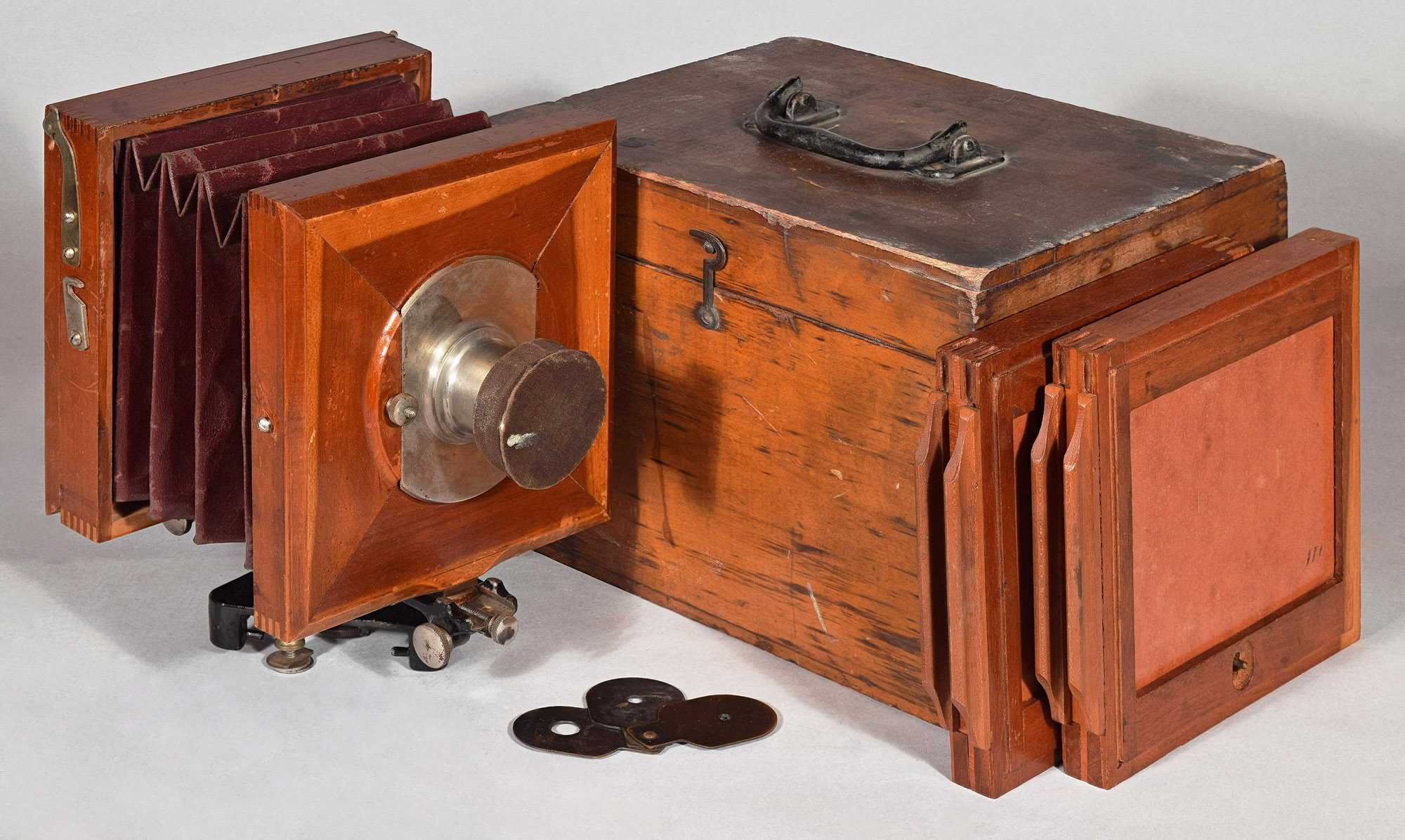
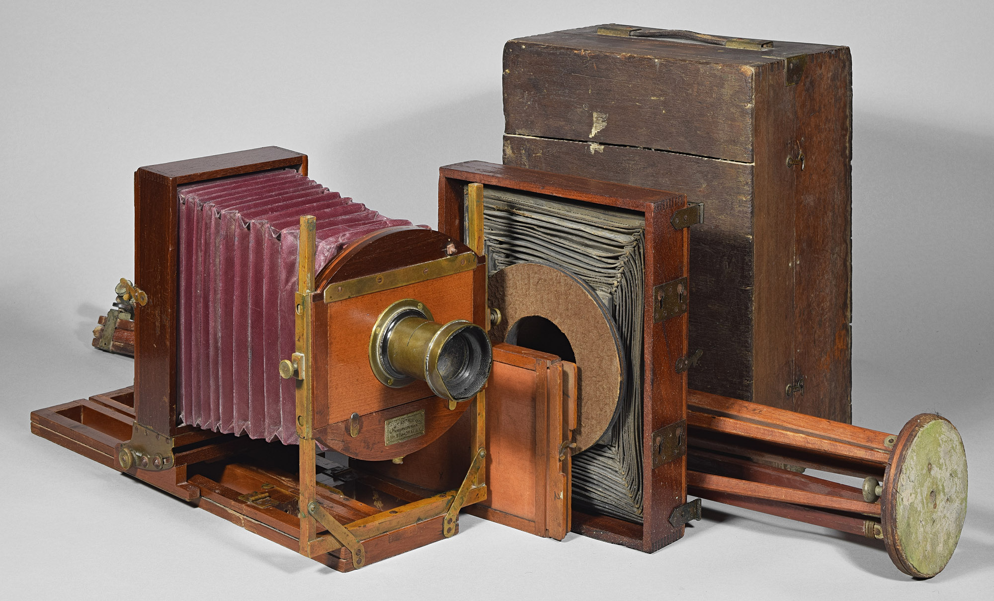
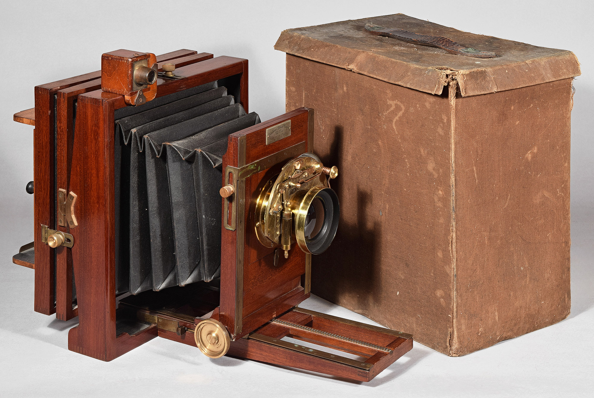
1.1 Scovill Mfg. Co. View Camera Box, LP1071 5x5”, c.1875
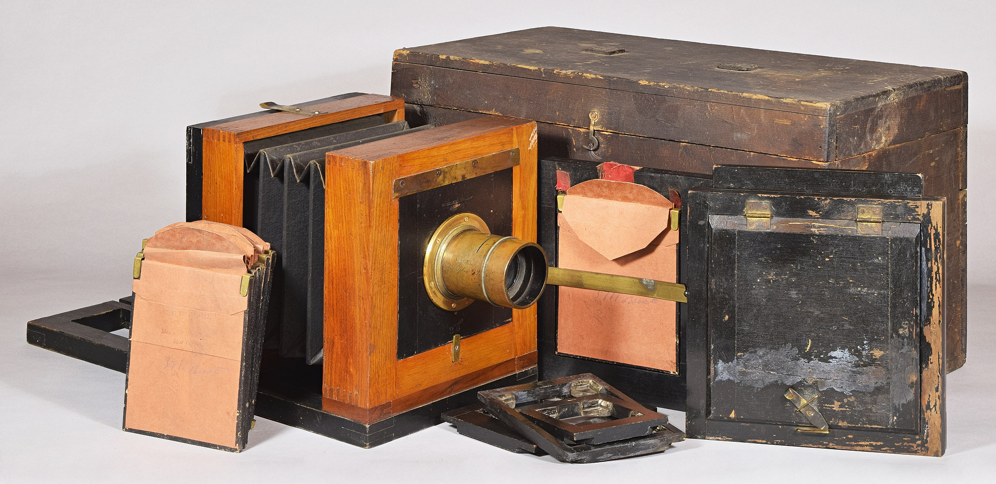
The name of this camera model, View Camera Box, is typical of the product lines of even large manufacturers like Scovill during the wet plate era. Catalogs of the 1870’s had few cameras, and fewer engravings or illustrations of what its cameras look like. As the trouble and expense of wet plate photography was beyond most hobbyists, the cameras in catalogs of that era were manufactured for professionals, who would not mind the mixed black and stained finish of this utilitarian camera. This camera has a non-folding bed, rare among cameras intended to be toted about in the field. In the 1870’s, non-folding bed cameras in the field were more often taken out of the studio, especially when of small size, such as this 4x5” Scovill. I expect that when the photographer was carrying wet plate materials including a darkroom of some kind, carrying a non-folding camera wasn't much more trouble. That the owner built a wooden carrying case for this camera and its accessories indicates that it was taken in the field frequently.
The plate holder shown is a wet-plate holder, but to its left is a square, black, insert that can hold a 4x5 dry plate (in orange paper wraps). Five more wrapped plates are on the far left. The insert can be placed in any orientation inside the plate holder, which can only be installed in one direction. Thus, the insert provides the ability to switch formats.
1.2 E. & H.T. Anthony Success Compact View Variation 3, LP207 8x8”, c.1875

The plate holder to this Success Compact View has glass corners. Normally, photos would be taken using 8x8" wet plates. This holder, like the previous one, appears to be only able to be installed in one orientation. Photographers sometimes drew a series of horizontal and vertical pencil lines on their ground glass, so they would know how to aim the camera for one format or the other. In addition, kits (not shown) could be had that fit within the corners and would hold smaller plates, such as 4x5” or 5x7”. The kits could be installed either for vertical or horizontal format without changing the position or focus of the camera.
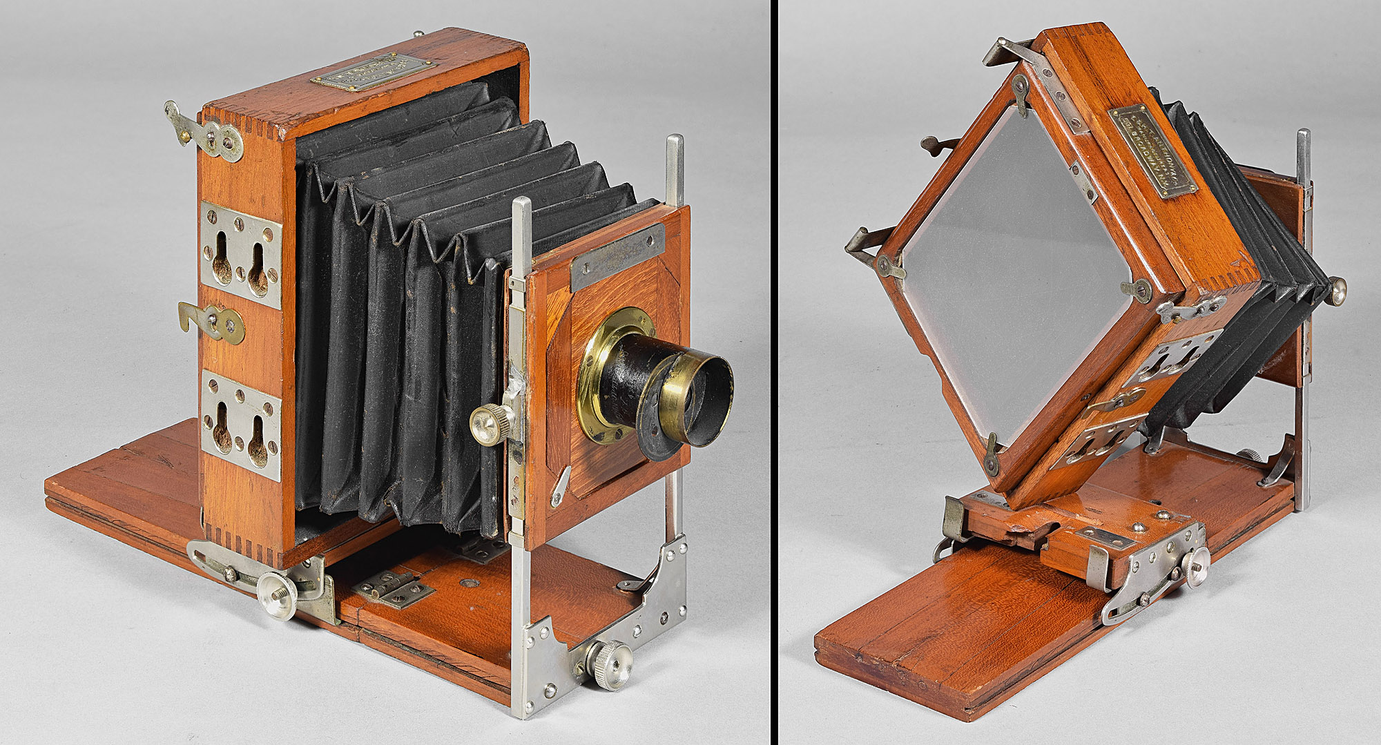
1.3 J.A. Anderson
New
View, LP350 10x10”, c.1885
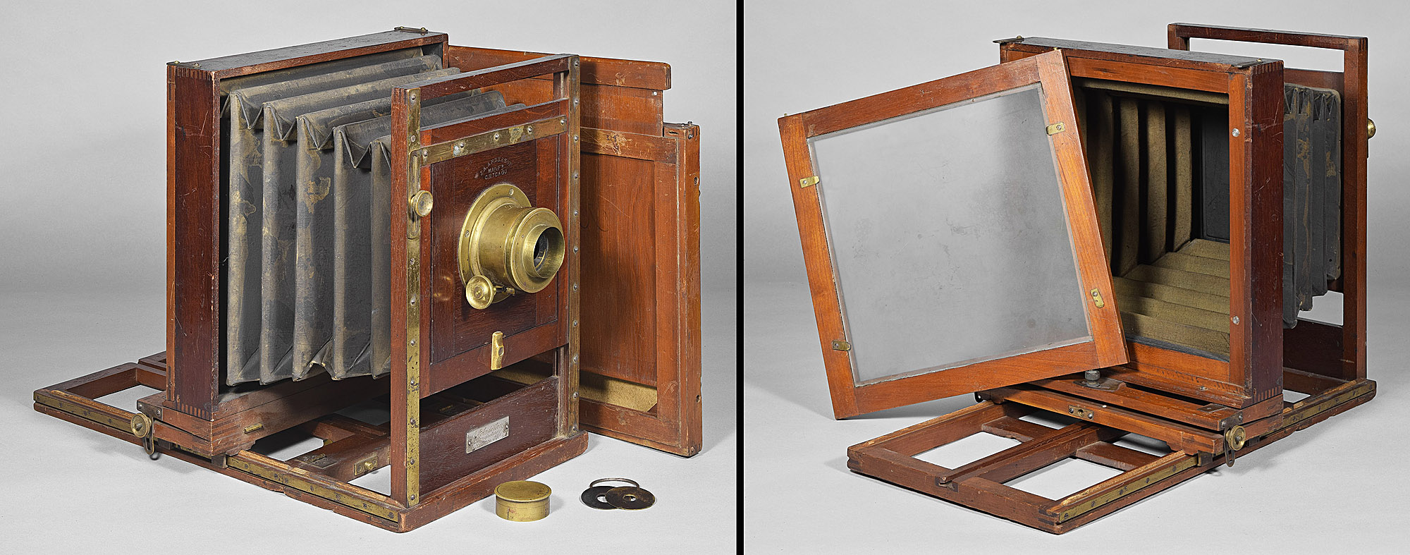
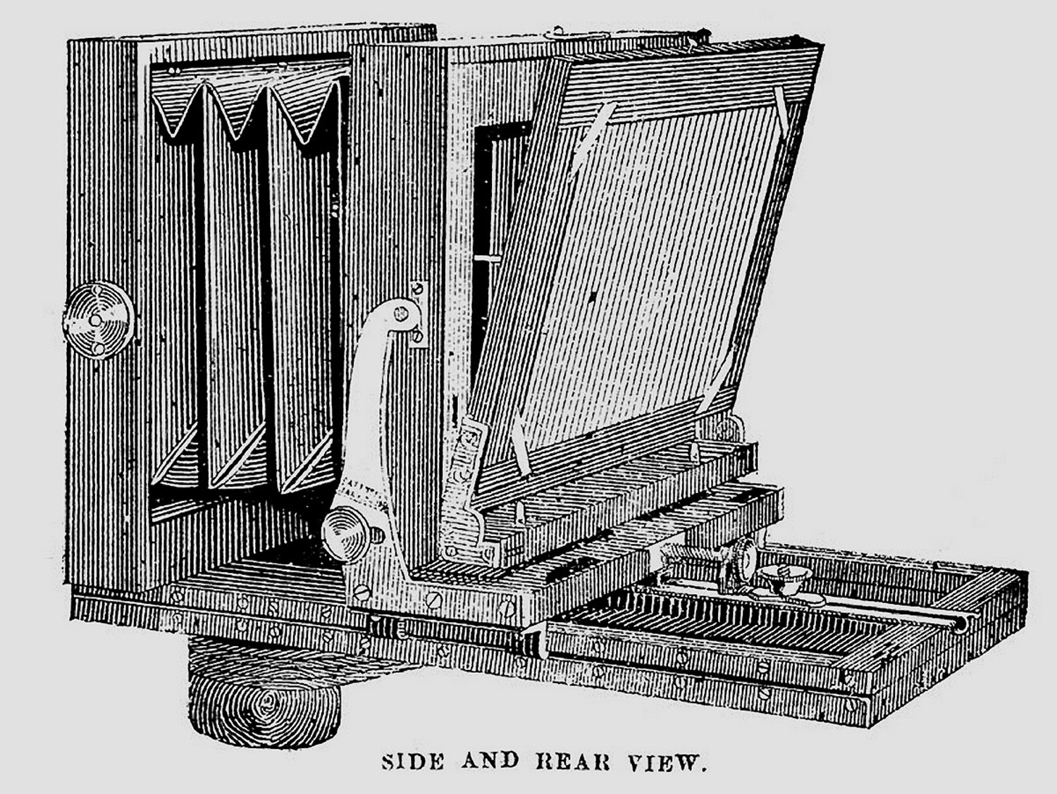
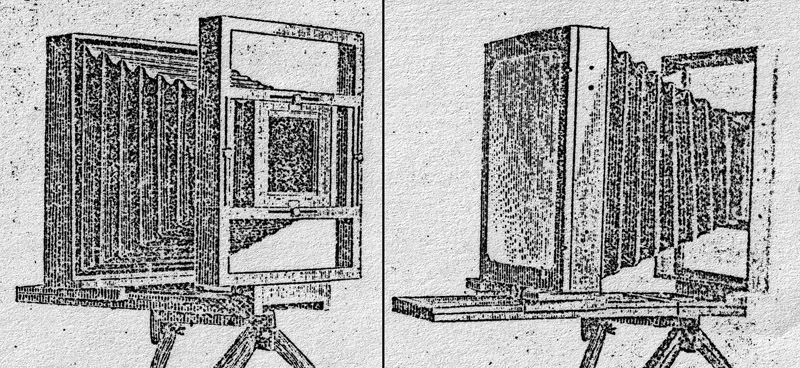
Despite its name, the New View is a dry plate era camera essentially no different than the wet plate cameras above. The holder, shown behind the camera and shown in detail in the engraving below, can be adjusted to hold a variety of sizes of rectangular plates, as well as being set up before loading for either vertical or horizontal format, as shown in the engraving.
No. 7 Catalogue, T. F. Indermill, St. Joseph, MO, October 1,
1885, p. 94
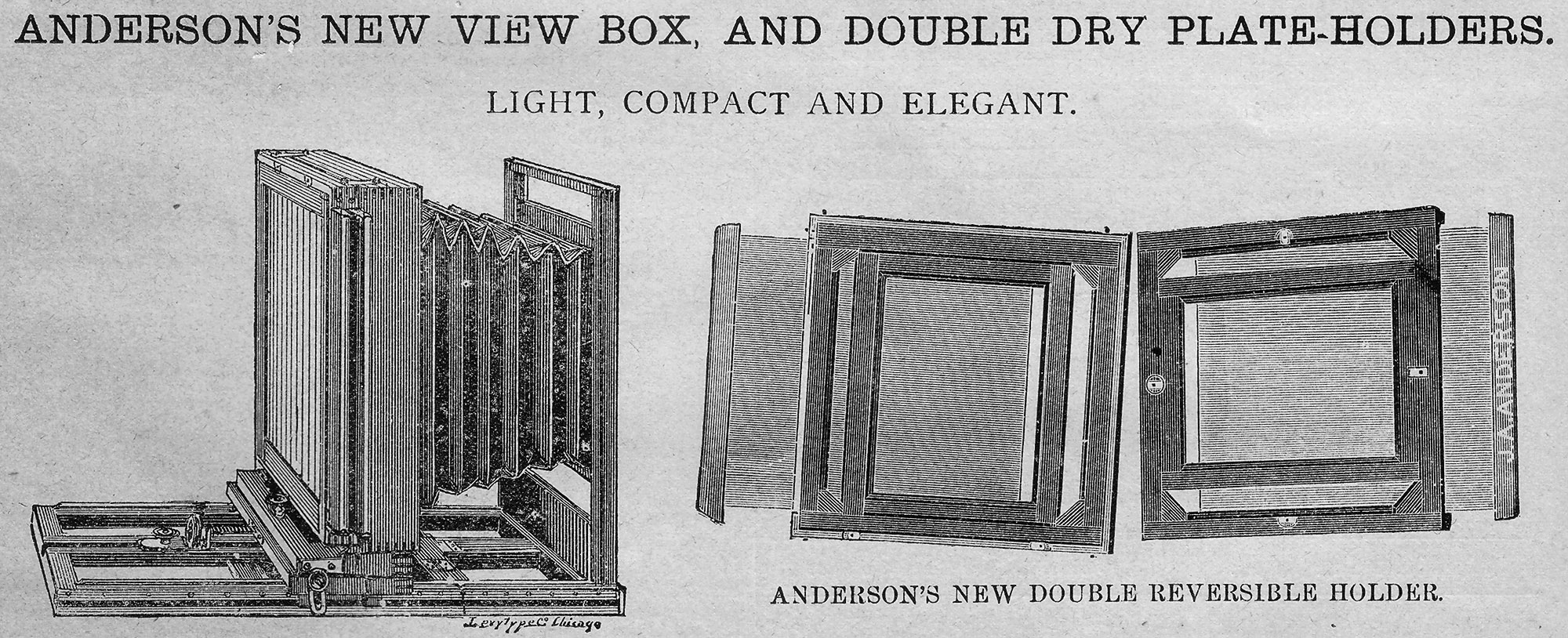
The engraving of the plate holder, above right, shows the arrangement for
vertical and horizontal format.
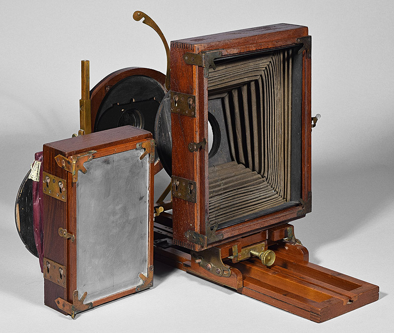
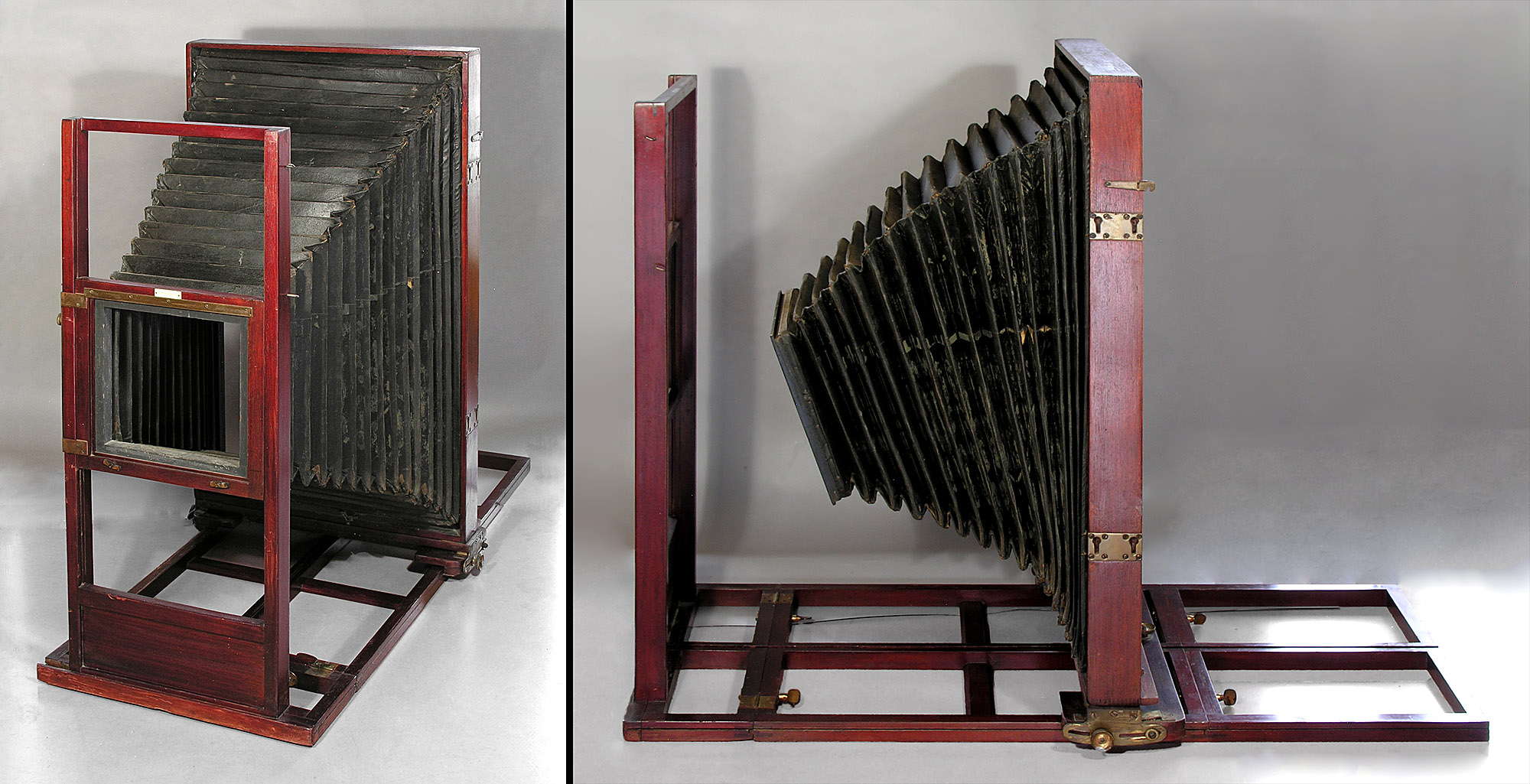
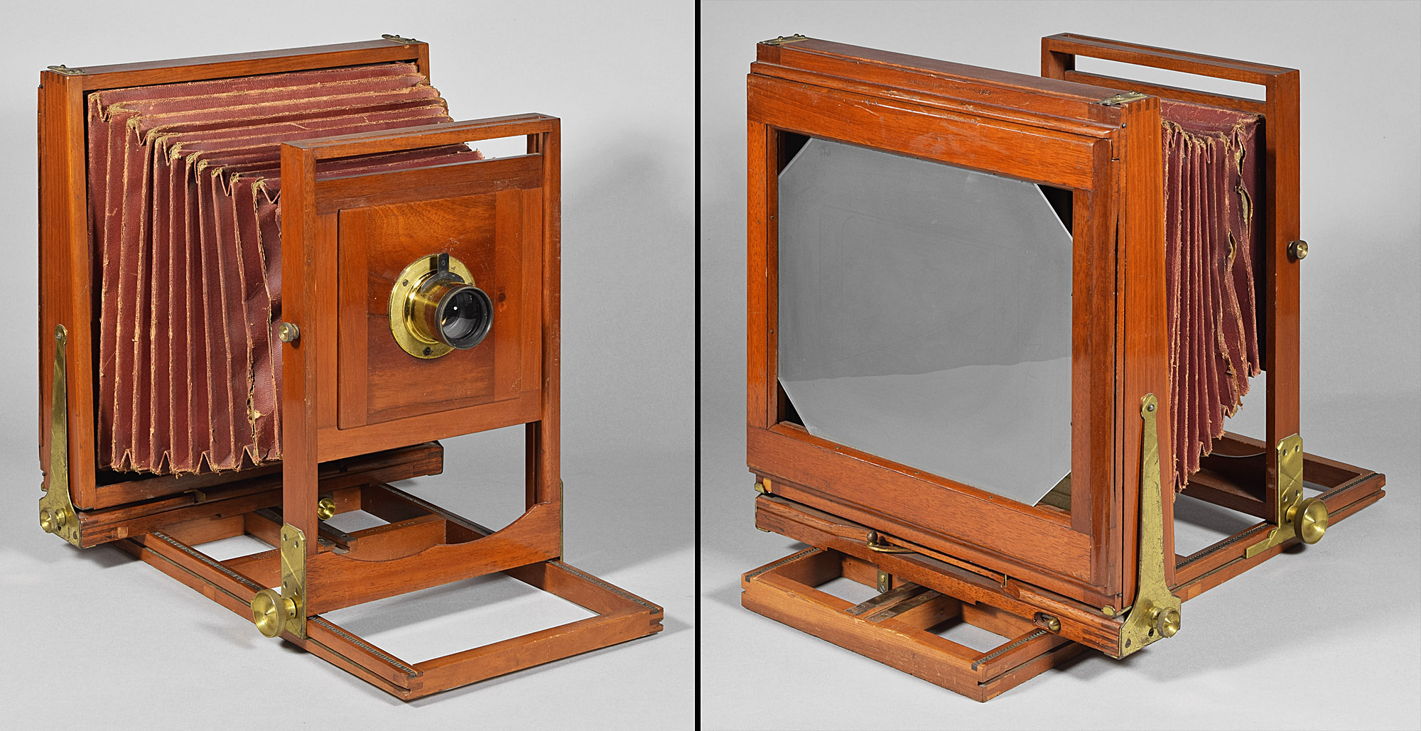
1.4 J.A. Anderson Anderson’s View or Anderson’s Compact View, LP1245 14x17, c.1890
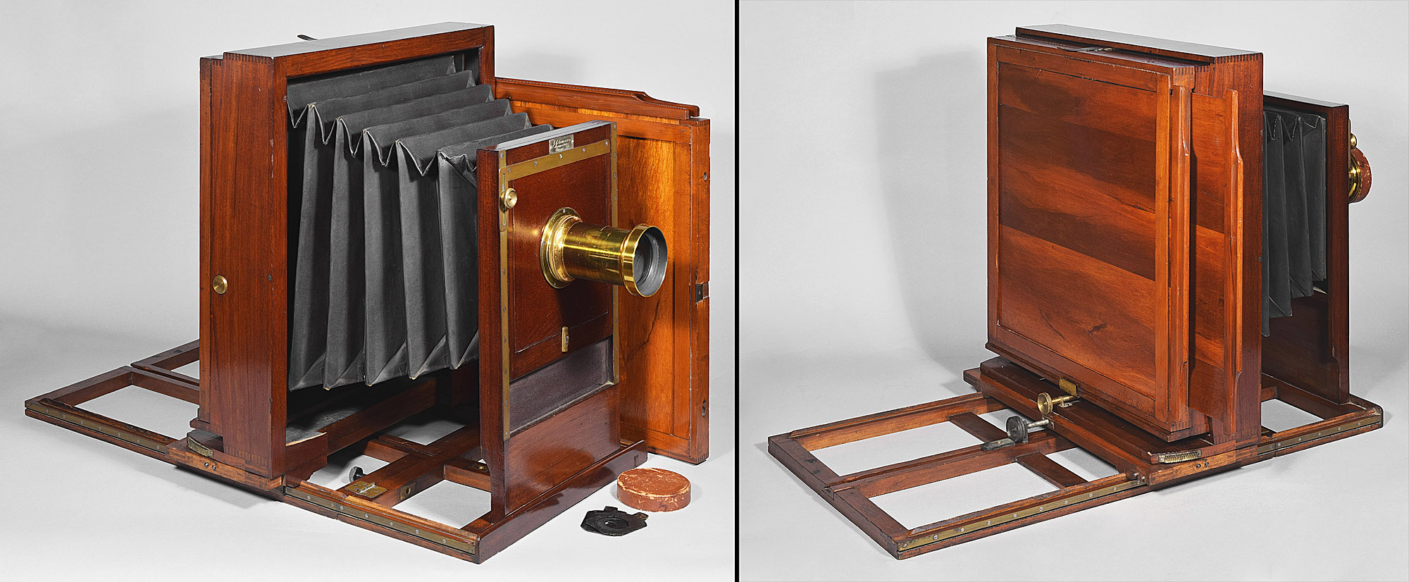
The model name of the camera above could be one of two: The name Anderson’s View Box is not ever mentioned in Anderson literature or advertising – it was invented as the precursor of Anderson’s New View (No. 1.3 above). The name Anderson’s Compact View is mentioned in advertising but not described or depicted in an engraving. It is essentially identical to a known Anderson studio camera, Anderson’s Extra Quality Portrait Camera, perched upon a reduced thickness and folding platform. Its plate holder appears to be identical to the dry plate holder with the New View above, with its internal adjustable sizes and orientation, except it is stained and lacquered rather than painted.
2. a square plate holder that may be
installed in two 90 ⁰directions
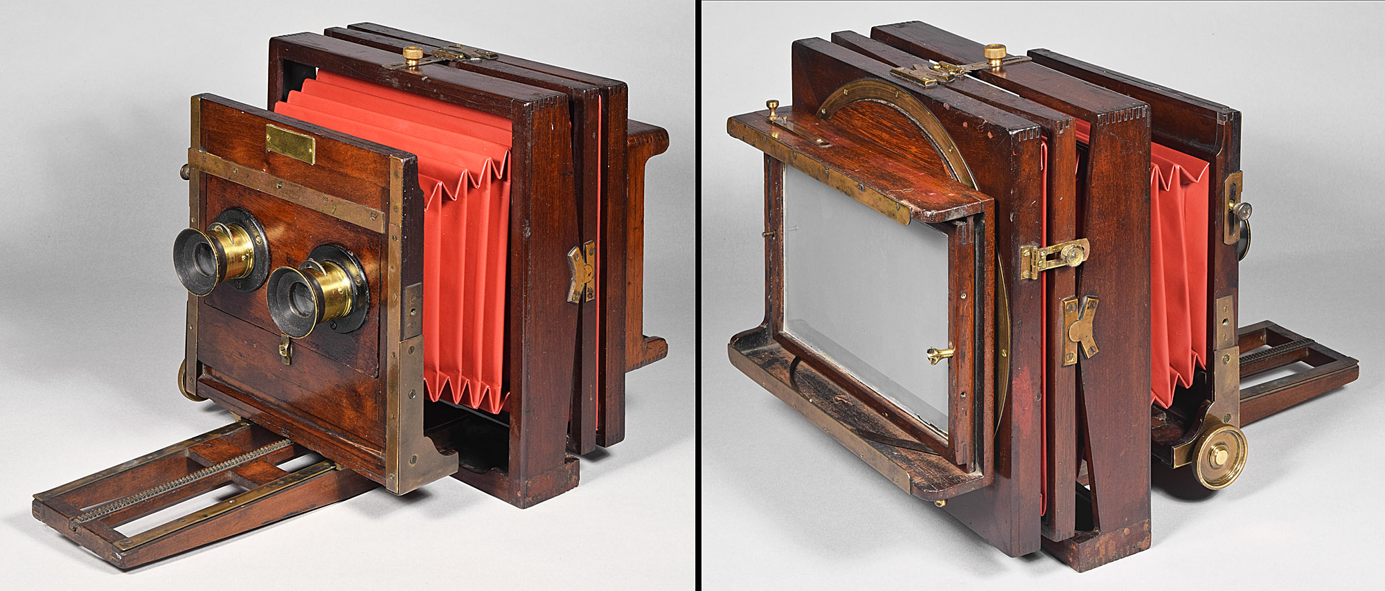
2.1 Rochester Optical Co.
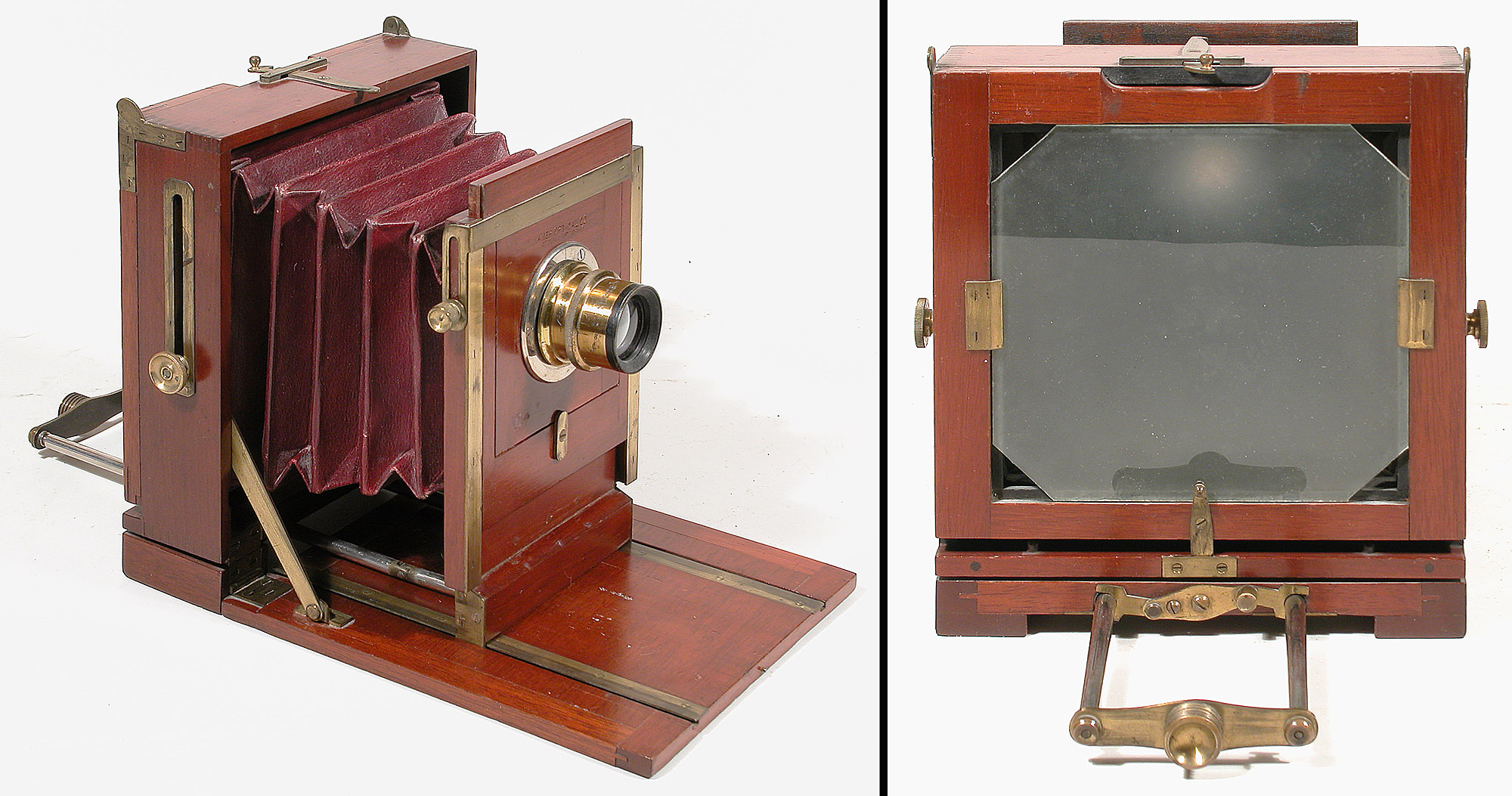
American Challenge Camera, LP609 4x5”, c.1883
The design of William Walker, this innovative monorail camera was made by the Rochester Optical Co. for a year or two. The monorail has a built in tripod head and the camera is only capable of being oriented one way - so that the sliding metal flange of the lens can act as a rise/fall movement. The plate holders are for 4x5” plates only, but square in dimensions and constructed in such a way that they may be installed in two orientations, that is, with the dark slide pointed to the right or with the dark slide pointed up. The hinged back, as well as the plate holders are held in place by two small metal posts at the bottom and the two long spring-loaded clips on the upper sides. The posts and clips engage slot-like depressions in the holders – the front upper corners in the photo above show such slots on two adjacent sides of the holders.
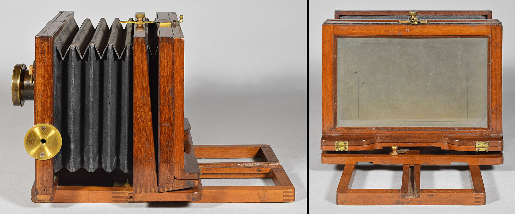
2.2 American Optical Co./Scovill Mfg. Co./Scovill & Adams Co. Flandreau, LP356 4x5”, c.1888-c.1896
The American Optical Flandreau has a similar approach to format as the ROC American Challenge Camera above. It has two posts at the bottom and two spring clips on the upper sides of the camera. In this case, the spring clips engage brads placed on the plate holders (although no holders are present to demonstrate this).
3. a camera that can be (supposedly)
easy to disassemble, its standards and bellows turned 90⁰ and
re-assembled
It was realized that square cameras and square plate
holders, as in Section 2, are naturally heavier than a rectangular
camera and rectangular holders would be. One of the first attempts
was to turn the entire top of the camera.
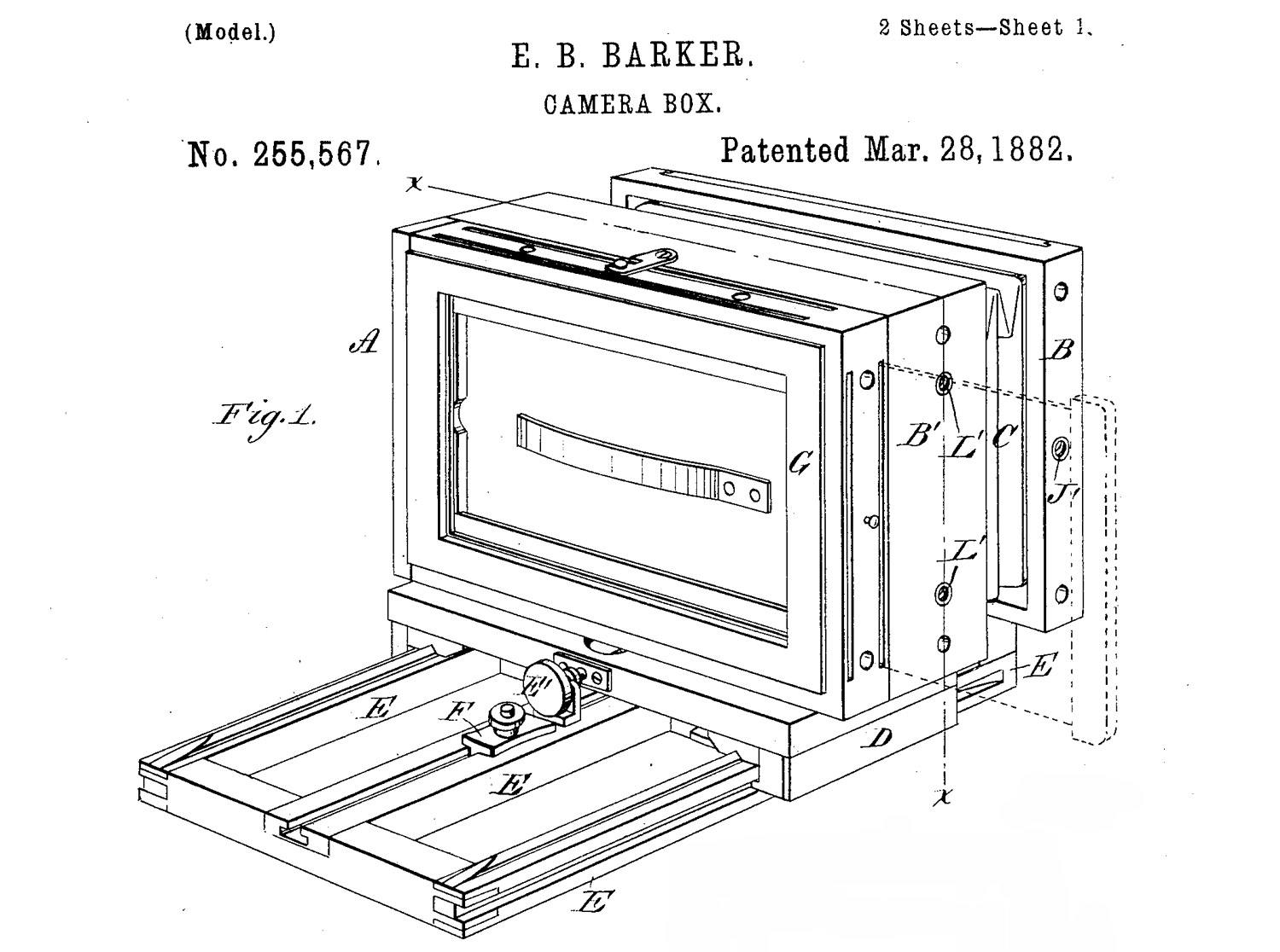
Erastus B. Barker, who abandoned his Daguerreotype
business in 1868 to go to work for E. & H.T. Anthony & Co., where he
became a prolific inventor. One of his patents addressed the
format change of a rectangular camera by having three threaded holes (L,
L’ and J’ in the patent drawing below) which attach to the fixed and
movable platform of the camera with thumbscrews. Unfortunately,
while the format is being switched, the photographer is juggling the
platform, loose standards with bellows, and three loose thumbscrews.
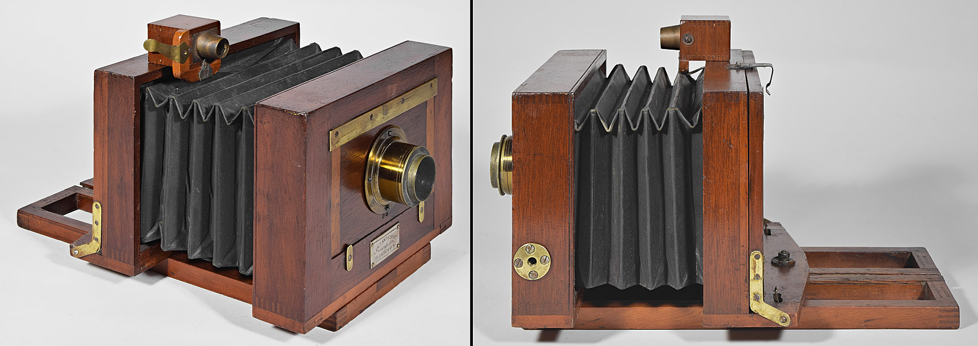
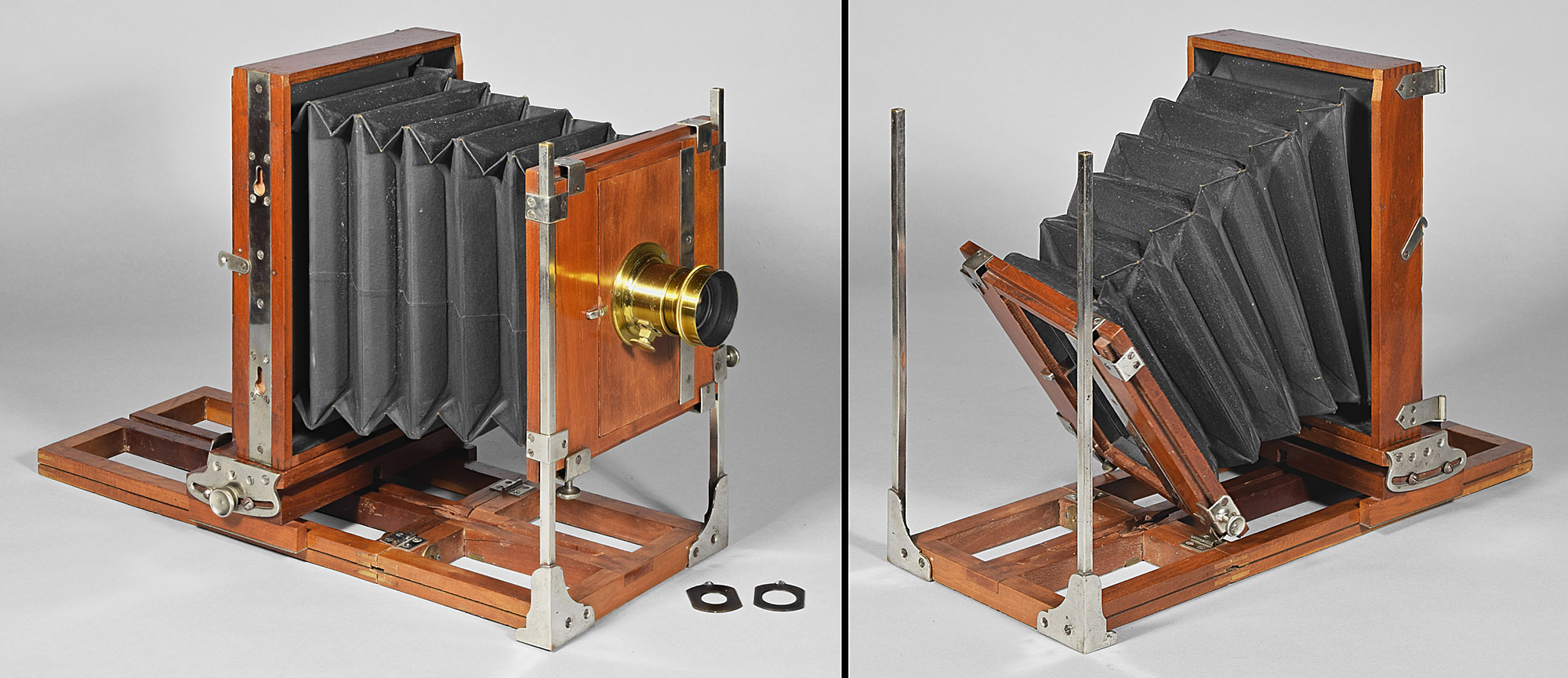
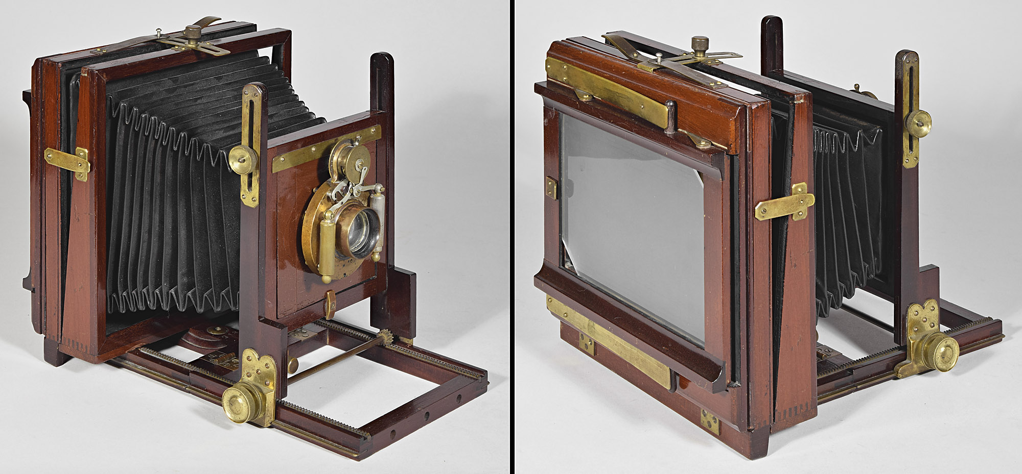
3.1 Anthony Novel Variation 1.0, c.1882
By the time Barker’s standard-flipping design was introduced to the public, in the April edition of Anthony’s Photographic Bulletin, just days after the patent date, it had been decided to decrease weight from the parallel bellows of the patent drawing to the tapering bellows and frame-style front standard below:
Anthony's Photographic Bulletin Vol. 13 April
1882, p. 160

The threaded holes can just be made out in the engraving at the left – the larger holes being threaded and smaller holes for guide rods. It still required the juggling act to change format.
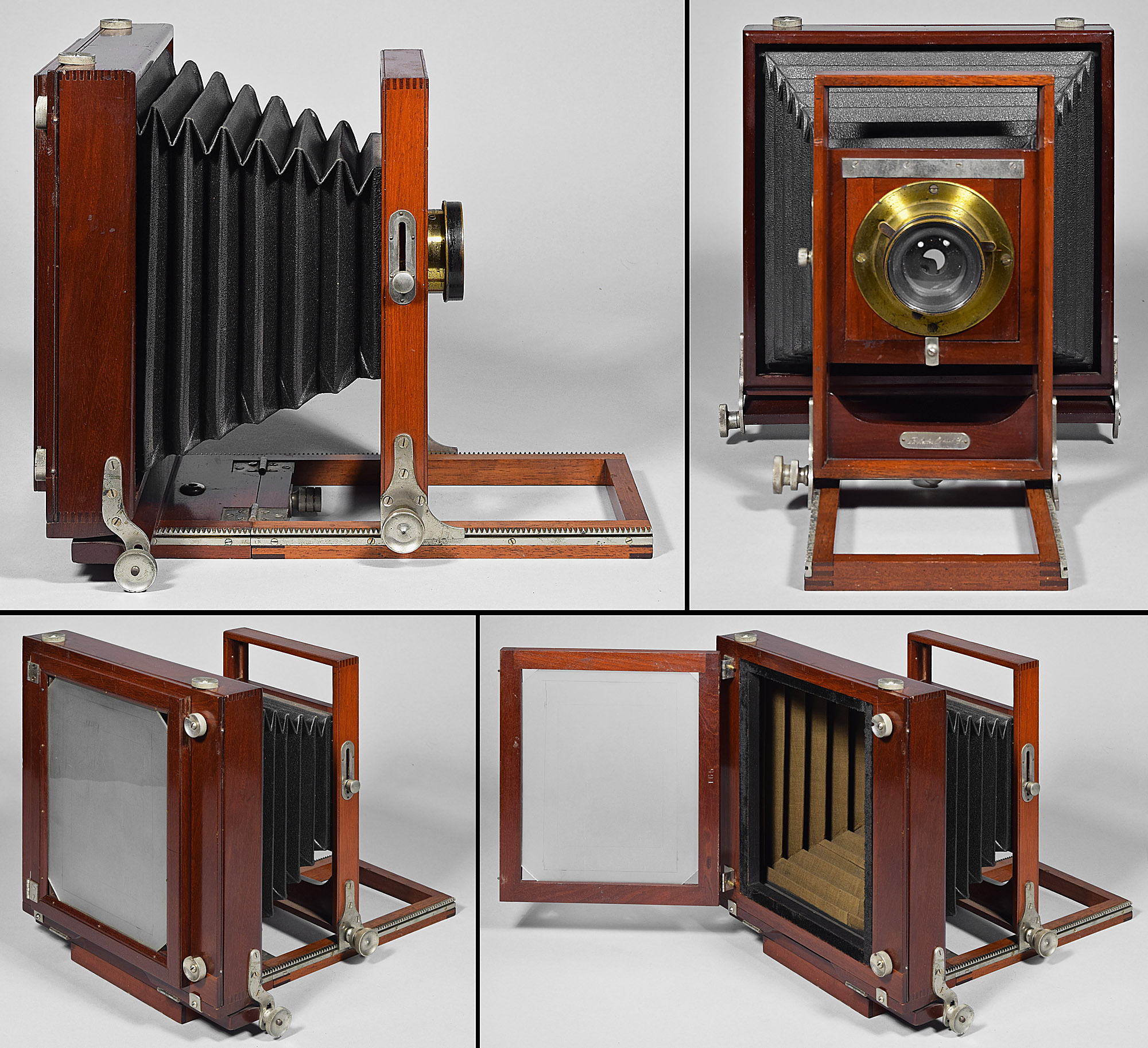
3.2 Rochester Optical Co. American Challenge Wooden Base Camera, LP290 5x8”, c.1883
Almost
contemporaneously to Anthony’s Novel View, the Rochester
Optical Co. manufactured a camera very much like Barker’s patent
drawings, except that it has four thumbscrews instead of three.
For some reason, they kept the name American Challenge Camera, despite
probably still manufacturing the monorail camera already named the
American Challenge Camera. I added the additional name
Wooden Base to
distinguish the two models. This model also has a built-in tripod
head just like the other American Challenge Camera.
I have seen only three examples of this interesting
camera. As if to accentuate one of the problems with taking a
camera apart to change formats, the second one I saw (not illustrated),
despite being in its original carrying case, was lacking its entire
platform, someone having unscrewed it and subsequently lost it.
4. second tripod mount 90⁰ from the first
One of the easiest ways to change format in a rectangular camera is to have two tripod mounts, one for horizontal and one for vertical. Both E. & H.T. Anthony & Co. and Scovill Mfg. Co. utilized this approach as early as the 1870’s. Such cameras can be easily recognized by the large, round brass fitting, usually on its left side.
4.1 E. & H.T. Anthony Success Stereo View, c.1872
This engraving of Anthony’s Success Stereo View Camera begs the question “How does a vertical stereograph even work?”
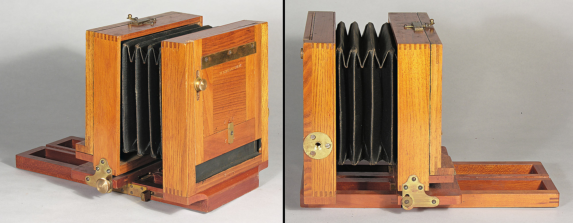
4.2 American Optical Co., Scovill Mfg. Co., Prop'rs “76” View Camera, LP1230 5x8”, 1876-1898
The camera depicted here had
several names during its long production run:
In the
Photographic Times 5, July 1875, pp. 168-169, it was introduced
as the Pocket Camera.
In the
Photographic Times 6,
March 1876, pp.
65-170, there are three sizes; the 4x4" and 4x5" sizes are the
Pocket Camera; the
5x8 size is The "76" Pocket Camera - "76"
because its production started in 1876.
In
The Photographer's Friend, 7th ed.,
Richard Walsl (Baltimore, MD) Catalog, 1882,
p. 51, it appears to be offered under the general term
AO's Dry Plate Outfits for Amateurs.
From
How to Make Photographs and Descriptive Price List,
Scovill Mfg. Co., distributed by C.H. Codman (Boston, MA),
1883, p. 13 through 1886, as AO's Apparatus Outfits.,
sizes up to 6½x8½" - the 5x8" size is also known as The "76"
Camera.
From 1887 through at least 1896, as Centennial Outfits.
- Centennial because 1876 was U.S.A.'s centennial.
While Scovill
made a number of small, straight bellows, back focus cameras at various
price points, the "76" Camera appears to be the only American
Optical Co. camera made on this general pattern: utilitarian in design,
yet elegantly finished, and the least expensive camera model that
American Optical offered throughout its run. The other cameras in
the American Optical Co. line are cameras having unique or elaborate
details, such as Flammang's Patent Revolving Back Views, to be
discussed below.
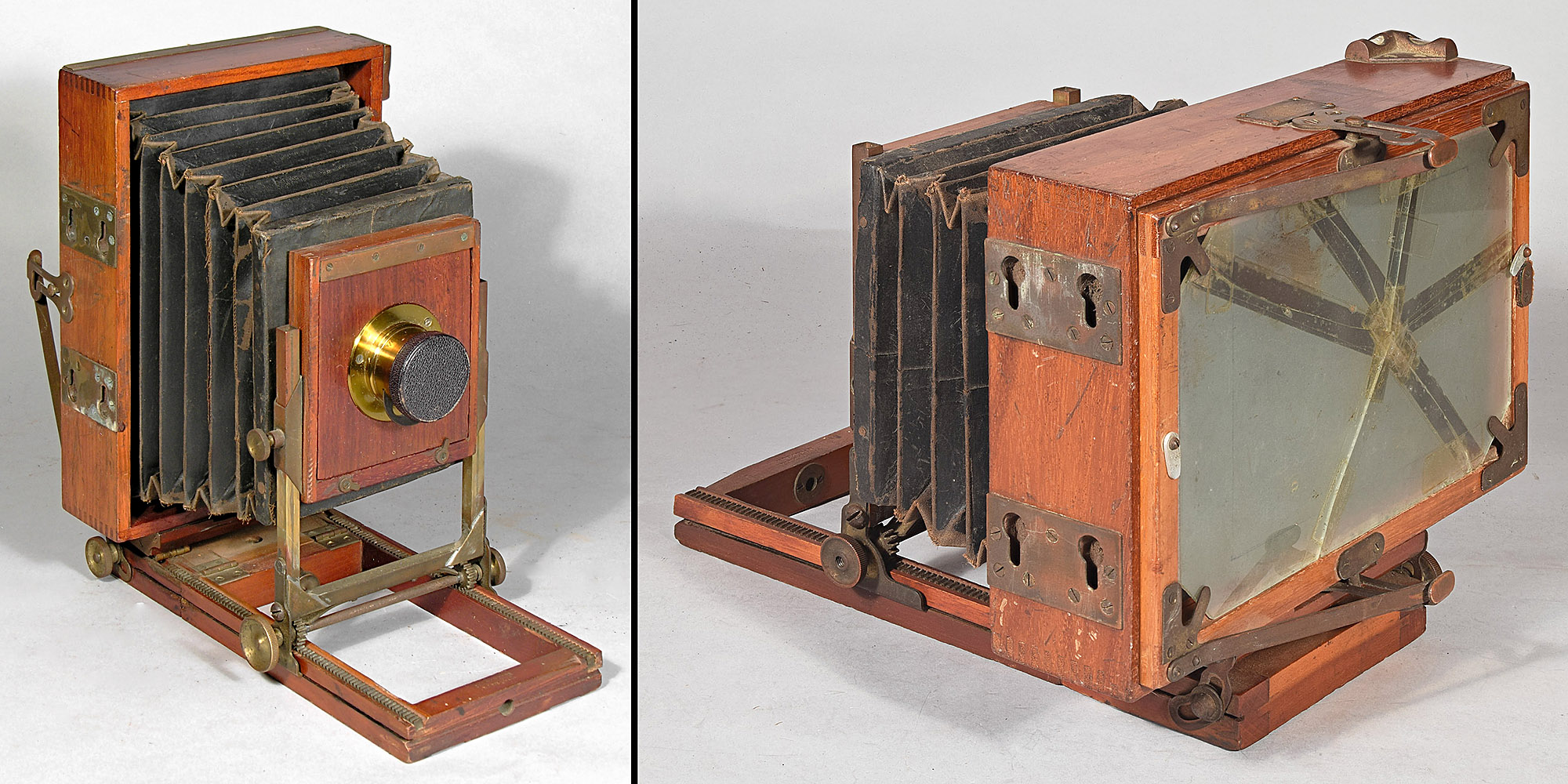
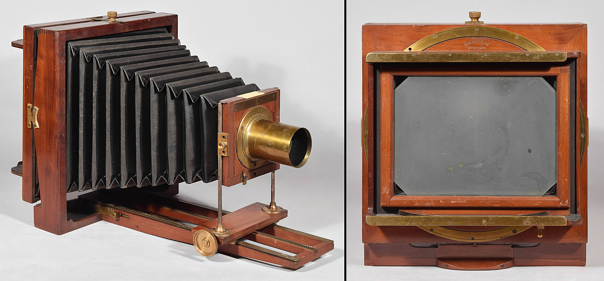
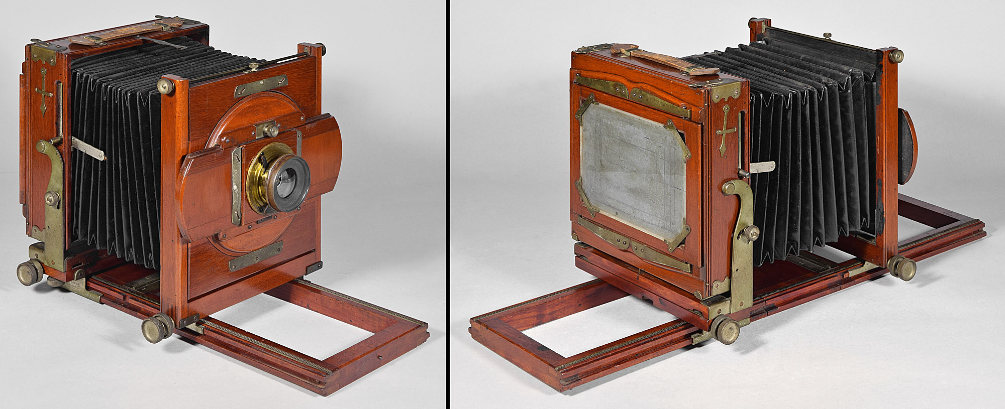
4.3 Scovill Mfg. Co. Scovill-type Waterbury View Variation 1, LP940 4x5”, 1885-c.1898
One of the most common view cameras of the 1880’s, The Scovill Mfg. Co. Waterbury View was inexpensive yet functional. One of its innovations over previous similar Scovill view cameras was the incorporation of Mathias Flammang’s patented rod and cylinder-type device (the brass fixture along the right side of the platform). Flammang was to Scovill as Barker was to Anthony – their inventive genius. The most common of the Waterbury cameras is made from a light-colored wood that is straight-grained sycamore (although often referred to as mahogany ). I call this type of Waterbury a Scovill-type because it is always stamped with a Scovill manufacturer stamp and there appears to be another different kind of Waterbury connected to American Optical. The Scovill-type Waterbury's wood and hardware are varnished. They always have serial numbers ranging up to 4 digits.
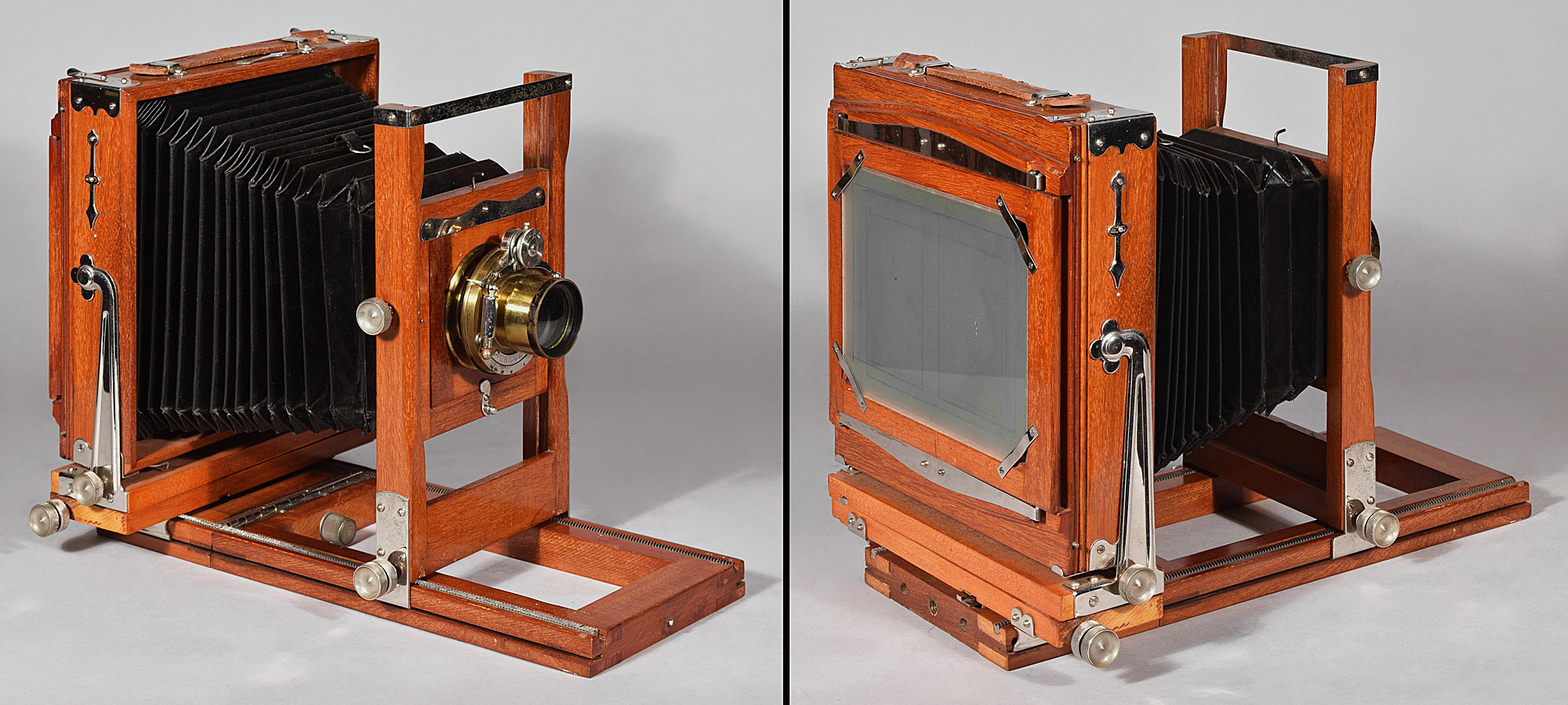
4.4 American Optical Co. American Optical-type Waterbury-type View Variation 2, LP572 5x7”, c.1890
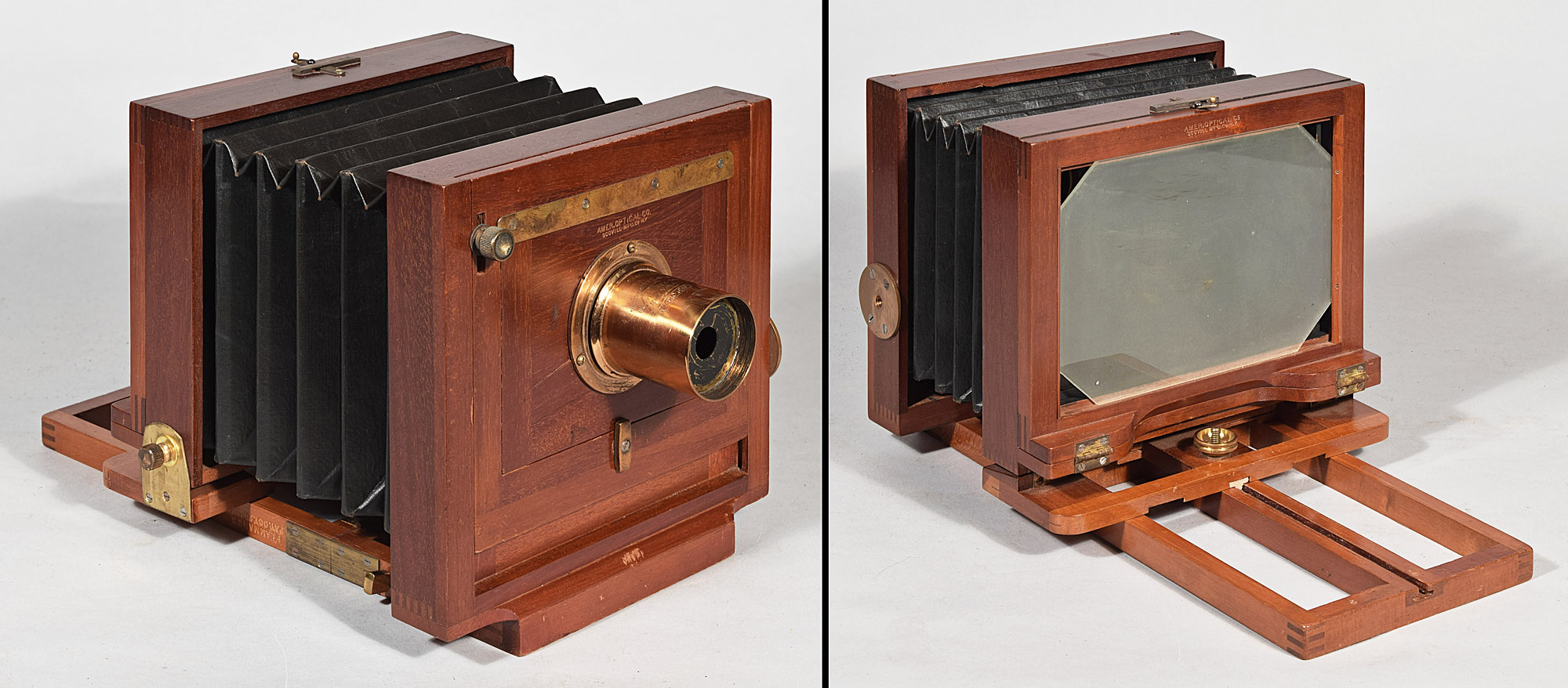
The relationship of this camera to the
Waterbury in No.
4.3 is fairly obvious (ignore the different shape of their flanges for
rear tilt at the lower rear standard – the No. 4.3 type also shows up
with the exact shape flange as seen in No. 4.4). However, there is
one major distinction: the No. 4.4 type is made of dark-grained mahogany
and is finished by the method known as French polishing, during which
shellac is rubbed over and over into the open grain of the wood until
the grain is filled in, creating a smooth and lustrous surface.
The metal of this type is also finely finished with what is called draw
filing, during which a file is used to smooth the metal and screw heads.
These are most often stamped with American Optical
manufacturing stamps, although they sometimes have Scovill stamps and
sometimes no stamps at all. They also have no serial numbers, but
often but not necessarily have assembly numbers, usually less the 50.
4.5 E. & H.T. Anthony & Co. Manhattan View, LP1327 5x8”, 1889-c.1892
The Manhattan View was a relatively inexpensive Anthony view. It was one of the few models c.1890 that was still made without a folding platform. Non-folding platforms had largely died out by then probably because of the huge carrying case required to fit it.
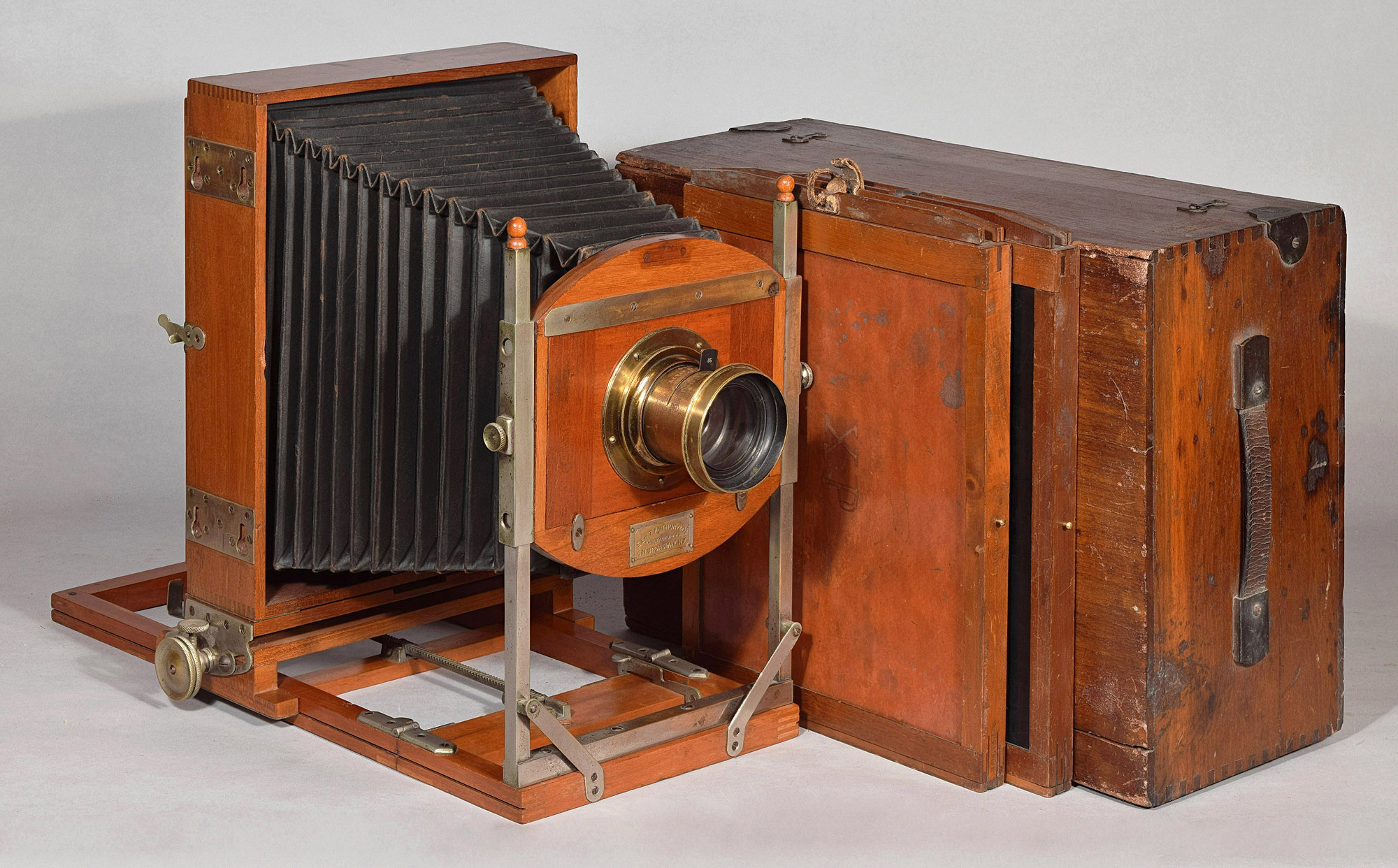
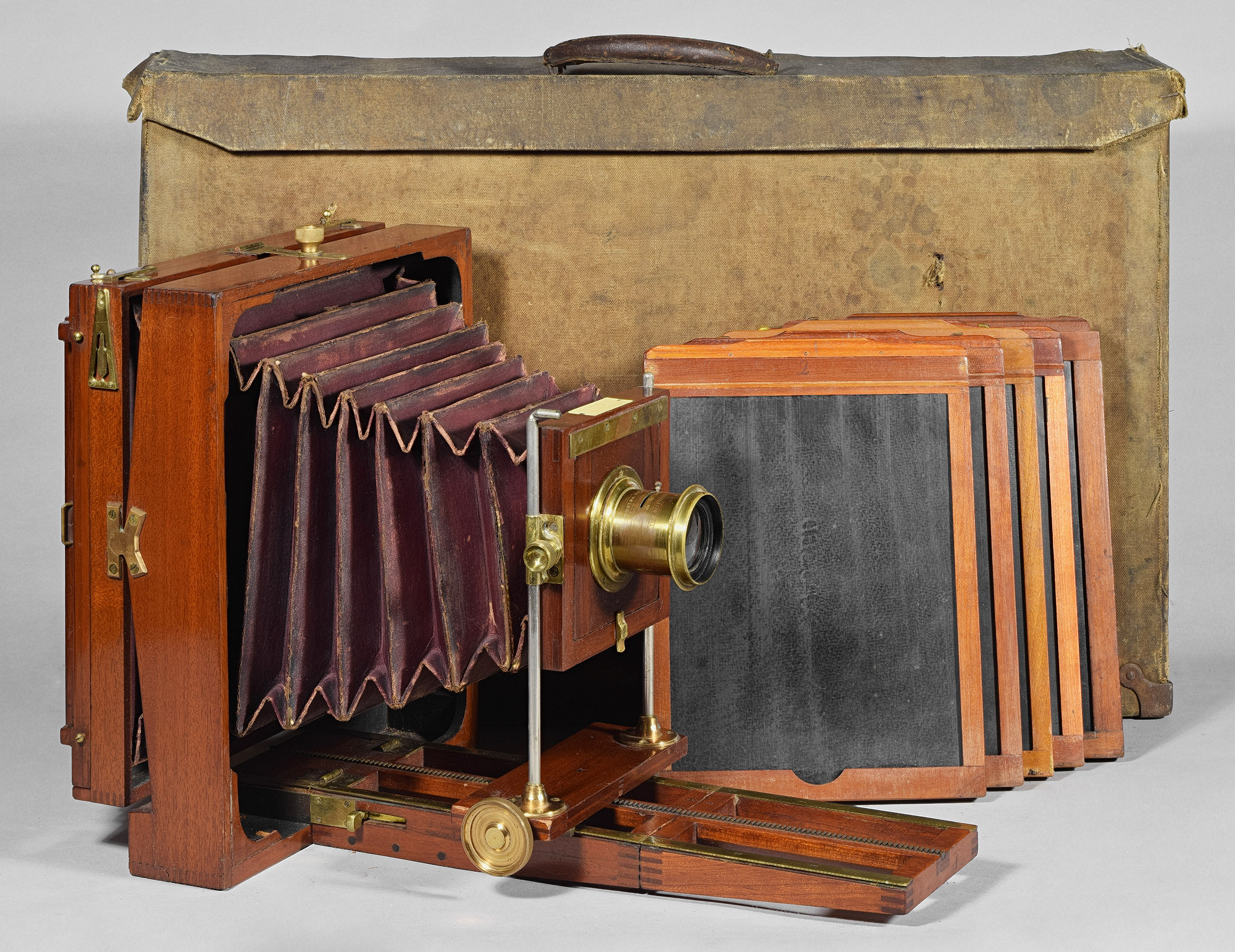
4.6 E. & H.T. Anthony & Co. Victor View Variation 1, LP830 4¼x6½”, 1889-c.1897
The Victor View was a very popular Anthony model of the 1890’s. It was very light and compact. It was also very finely finished (French polish and draw filing). Although it was not one of Anthony’s top of the line models, it was top of the line enough to rate a lightweight canvas carrying case instead of one made of wood. Ironically, the top of the line canvas cases for view cameras 1880-1915 usually did not survive until today, whereas the cheap wooden cases usually did survive.
5. a device to tilt a camera having one tripod mount
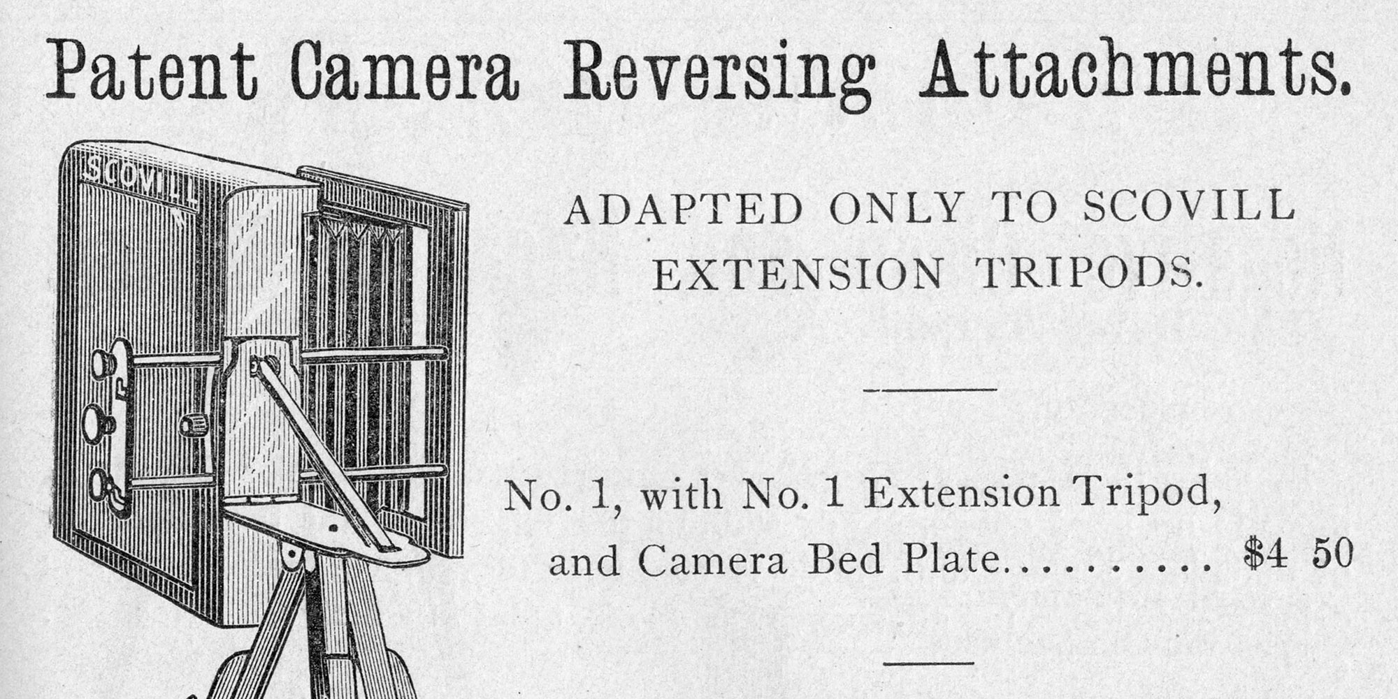
Mathias Flammang, long-time collaborator with Scovill Mfg. patented such a device on June 5, 1883. It was a metal framework that, when attached to a camera bottom, would allow the camera to be operated on a tripod with the framework collapsed, and would allow the camera to be tilted 90⁰ by extending the framework. The above engraving shows the device used with Scovill’s Tourist Pocket Camera from How to Make Photographs and Descriptive Price List, September 1888, Page 89, Scovill Mfg. Co., distributed by C.H. Codman, Boston, MA.
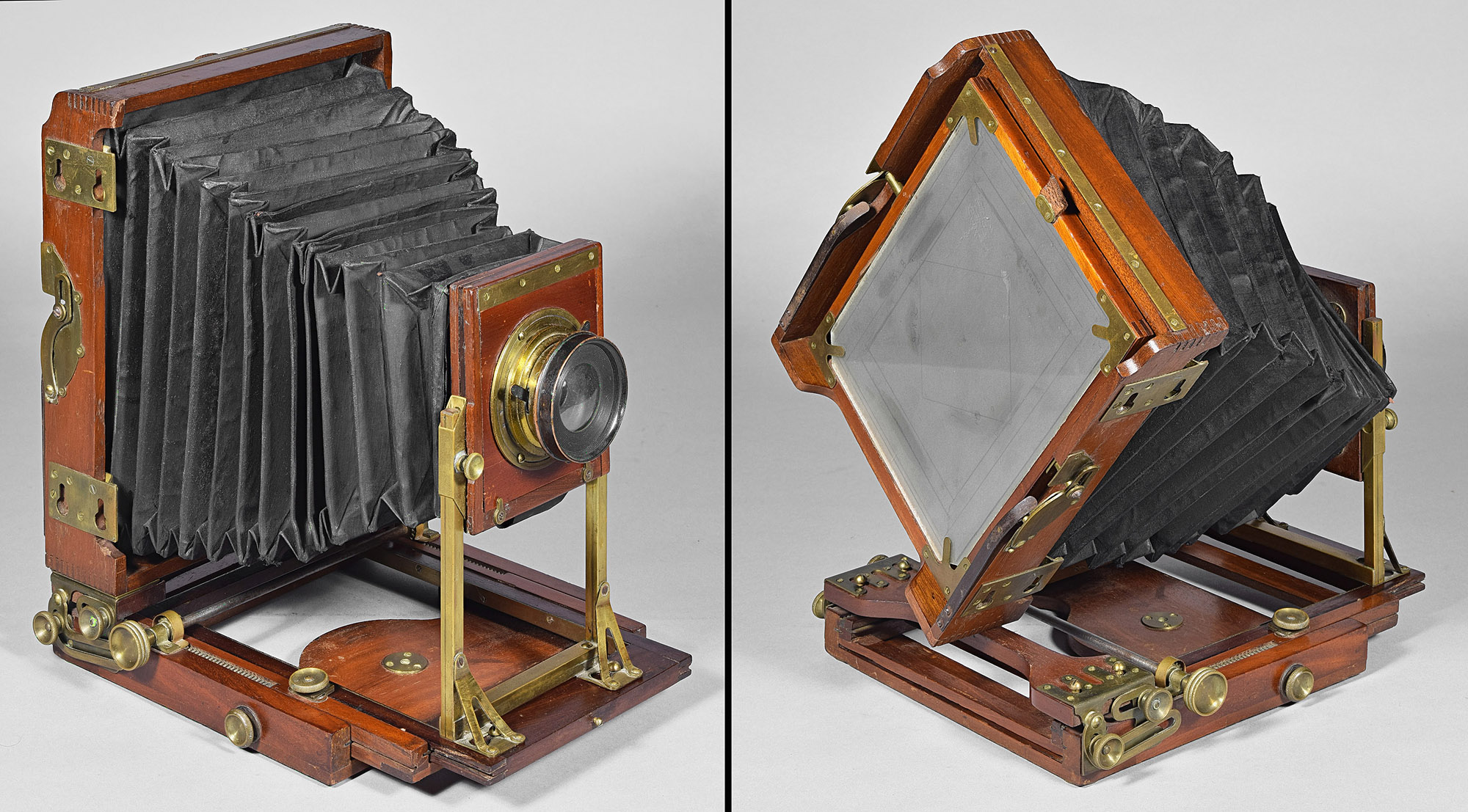
6. a bellows and rear standard that may be rotated together – E. & H.T. Anthony Novel View Cameras
Anthony realized soon after introducing the Novel View that disassembling a camera was not popular or that there were better ways of changing the format from vertical to horizontal. Anthony made a number of models: Novel View, Combination (Klauber) View, Novelette View, Duplex Novelette View, Front Focus Novelette View, Phantom View, and Fairy Novel View - all based on switching the format by 1) uninstalling the rear standard by disengaging key-shaped slots from screw heads on the movable platform, 2) rotating the rear standard and bellows via a freely rotating circular plate attached to the front standard, and 3) re-installing the rear standard to the movable platform by re-engaging the key slots and screw heads. Actually, as we shall see, all three of these steps were not involved until Novel View Variation 1.8. The variation descriptors used are meant to be in chronological order, although naming also depends on when a particular variation is encountered. hence the tenths used in variations.
6.1 Novel Variation 1.0, c.1882 – Bellows and Back Disassembled Instead of Rotated
This variation was already discussed in section 3.1 on cameras that disassemble to switch format, but is included here because it is an Anthony Novel View to make the section of Novel variations complete. It was introduced in the April edition of Anthony’s Photographic Bulletin as the Novel View. It may never have been manufactured, as I don't think one has ever been seen.
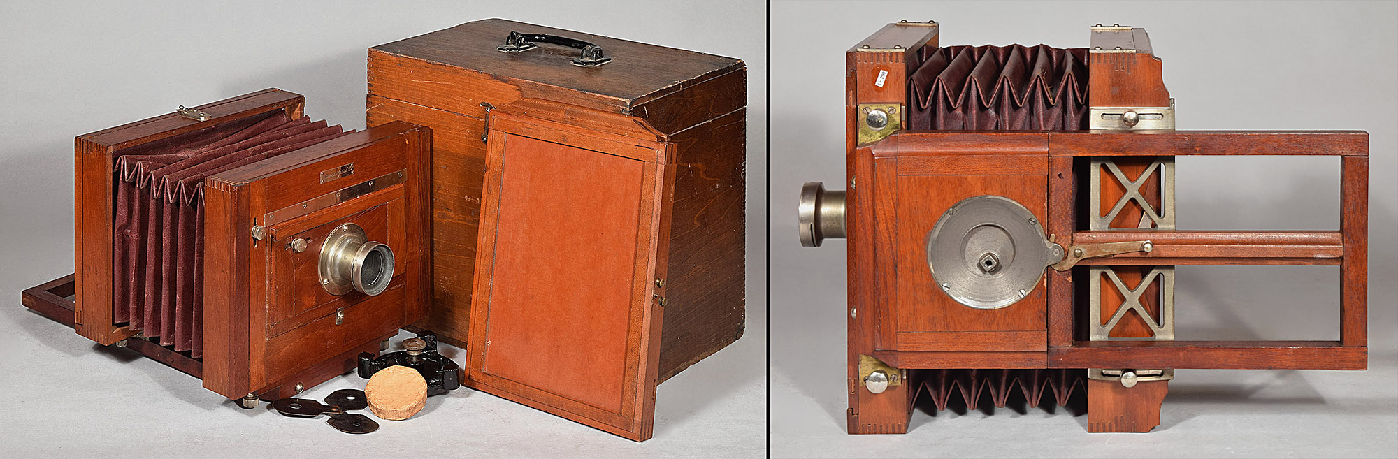
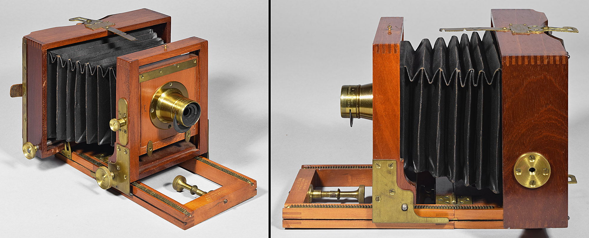
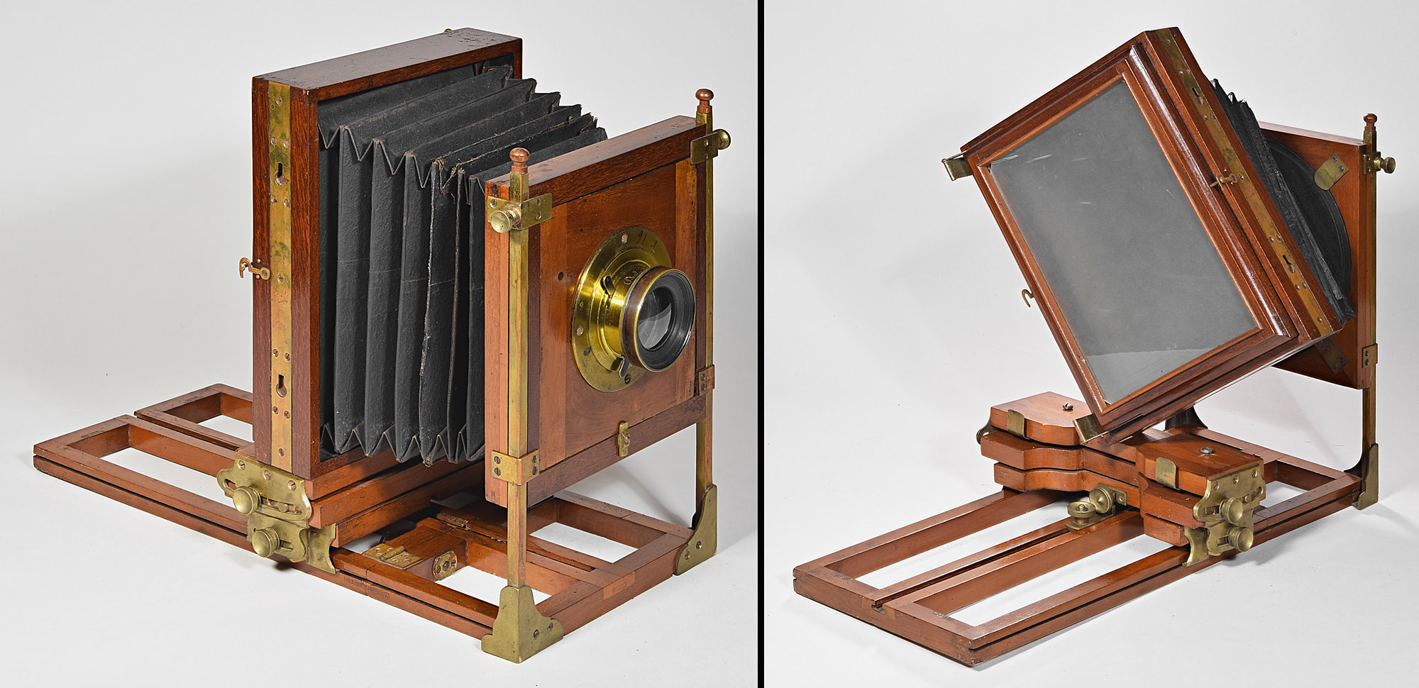
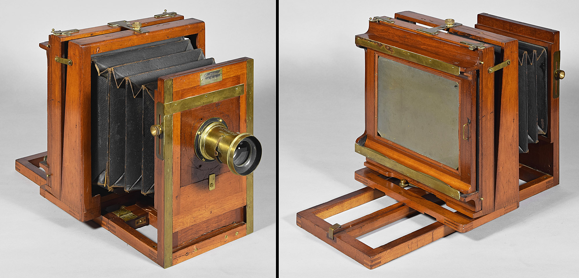
6.2 Novel Variation 1.5, LP1111 5x8”, c.1883
This is probably the first variation of the
Novel View
actually manufactured. It is the certainly the first to not
involve thumbscrews to hold the standards to the platform, like the
patent drawings and the introduction engravings show.
The inlaid metal strip that runs the full length of the
rear standard (and the full width of the rear standard on the bottom of
the rear standard as installed) has two key-shaped slots. Each of
these are sized so that the wider portion of its slot just fits over the
top of a large, round-head screw in the top of the movable platform (the
part whose end has a large plate and thumbscrew).
When pushed to the right (as viewed from behind), the
rear standard is freed from the keys and may be pulled upwards. If
the rise thumbscrew on the left (as viewed from behind) side of the
front standard is loosened, the entire wooden structure of the front
standard may be pulled off of the two square-shaped tubes on which it
normally resides. The right hand image above shows the front standard
after removal from the tubes. Now that the standards and bellows
have been removed from the platform, they may be turned 90⁰ to the right
(as viewed from behind). The front standard is then re-threaded
onto the tubes, and the alternate rise thumbscrew (the one that is on
the bottom of the front standard in the left hand image above) can be
tightened to install the front standard again. Finally, the rear
standard is positioned over the movable platform screw heads, and the
standard pushed sideways to the left (as viewed from behind) to complete
the format switch. Even though the top part of the camera is
separated from its bottom during the process, at least no loose screws
are involved.
This variation could not have been manufactured for
long, based on numbers of examples seen; in fact, it may be the only
example in existence.
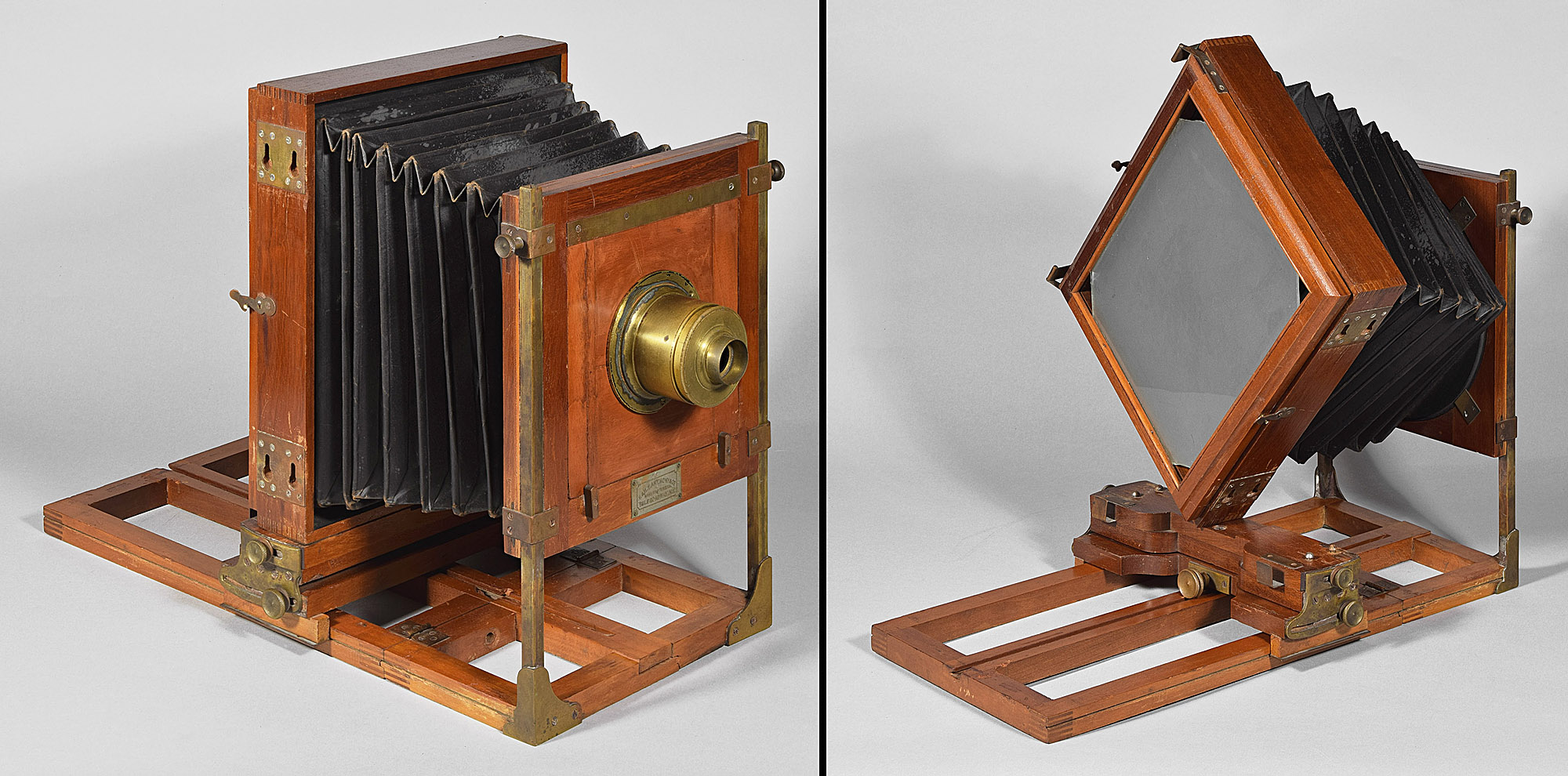
6.3 Novel Variation 1.8, LP1339 6½x8½”, c.1883
Still quite soon after the Novel View started manufacture, the design was
improved to include a round plate, attached to the back of the
front standard in a way to allow 360⁰ rotation. That way, the rear
standard and bellows always remain attached (unless it is desired to be
removed, as in the Duplex Novelette View)to the front standard, which,
in turn, stays attached (but movable for rise and fall) to the front of
the platform.
Despite its improved front attachment, the rear
standard has retained the long inlaid metal strip (although brass in
this case, instead of nickel-plated brass) running the length (and
hidden width) of the rear standard. Note the thick and gracefully
rounded frame in which the ground glass is held by slender strips of
trim. Also note the combination focus locking thumbscrew with
matching fine focus thumbscrew located at the lower middle of the moving
platform. Even though these were not visible in the Novel
Variation 1.5 images, they were not changed in Novel Variation 1.8.
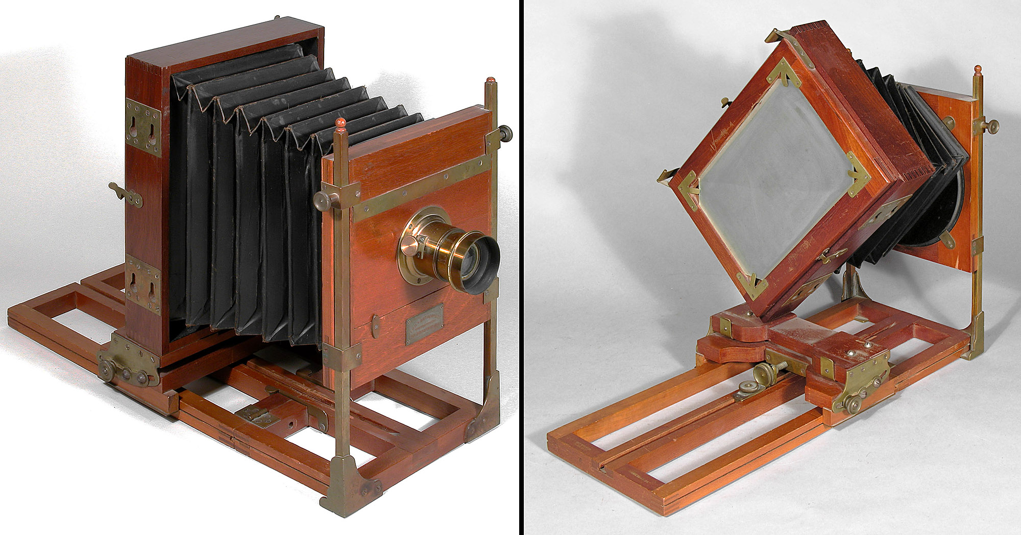
6.4 Novel Variation 2.0, LP1207 8x10”, c.1884-c.1888
The only change in Novel Variation 2.0 from Novel Variation 1.8 is that the long inlaid strip of metal with two key slots has been replaced with two robust brass plates, firmly attached to the rear standard using an astonishing eight screws apiece, and having two key slots each for a total of four key slots, up from two, for steadiness and strength.
6.5 Novel Variation 2.1, LP548, 11x14”, c.1885
![]()
This example is called Novel Variation 2.1 because its mechanics of changing format is the same as Novel Variation 2.0 - it could merely be an 11x14” version of Novel Variation 2.0. It has heavy duty cast brass fixtures to hold the front standard metal tubes, rather than the sheet metal fixtures for the smaller cameras in earlier variations. These are the same cast fixtures seen below in No. 5.7 the 14x17” Combination Novel View (Klauber View). It is possible, if larger sizes of those earlier variations were to be seen, they would also have the stronger cast fixtures. The profile of the ground glass frame is different than earlier variations as well, although that, too, may be determined by the size of the camera. The ground glass frame is not hinged as in smaller cameras, perhaps due to the weight of said frame and glass being prohibitively great for a hinge.
Plate Holder for
Novel Variation 2.1
![]()
These rectangular Novel cameras take rectangular plate holders. Since few of these early models have come with their holders, this one is shown here. It is very similar to studio holders, in that it is one-sided, and is loaded from the back. It has a solid wooden dark slide – a very early choice replaced with cardboard or Bakelite by even the middle 1880’s. It also has wire corners in the interior "kit" for reducing the size of plates to be used - it could be used for wet plate photography as well as dry plate - another early feature.
6.6 Novel Variation 3.0, LP139 5x8”, c.1887-c.1897
By 1887, Anthony cameras, even of models established earlier, received updates. The operation of this variation remains the same as the previous ones, but it has two new features: 1) It has Anthony’s patent (US 307,965; Nov 11, 1884) hooks for making the bed rigid. Each camera gets two of these, on each side of the center of the platform. Each hook consists of sheet brass cut to a hook shape, pivoting around the screw that secures it to the front of the camera, just ahead of the hinged platform joint. The hook part bears against a thick landing pad of brass on just after the platform joint to make, at least when new, the two parts of the platform fit together tightly. 2) Brass corners to hold the ground glass instead of pieces of trim wood. These would require much less hand work than previously. They must be installed on a flat, which also eliminates the more expensive rounded profile previously used.
6.7 Combination Novel (Klauber Camera), LP413 14x17, C.1884
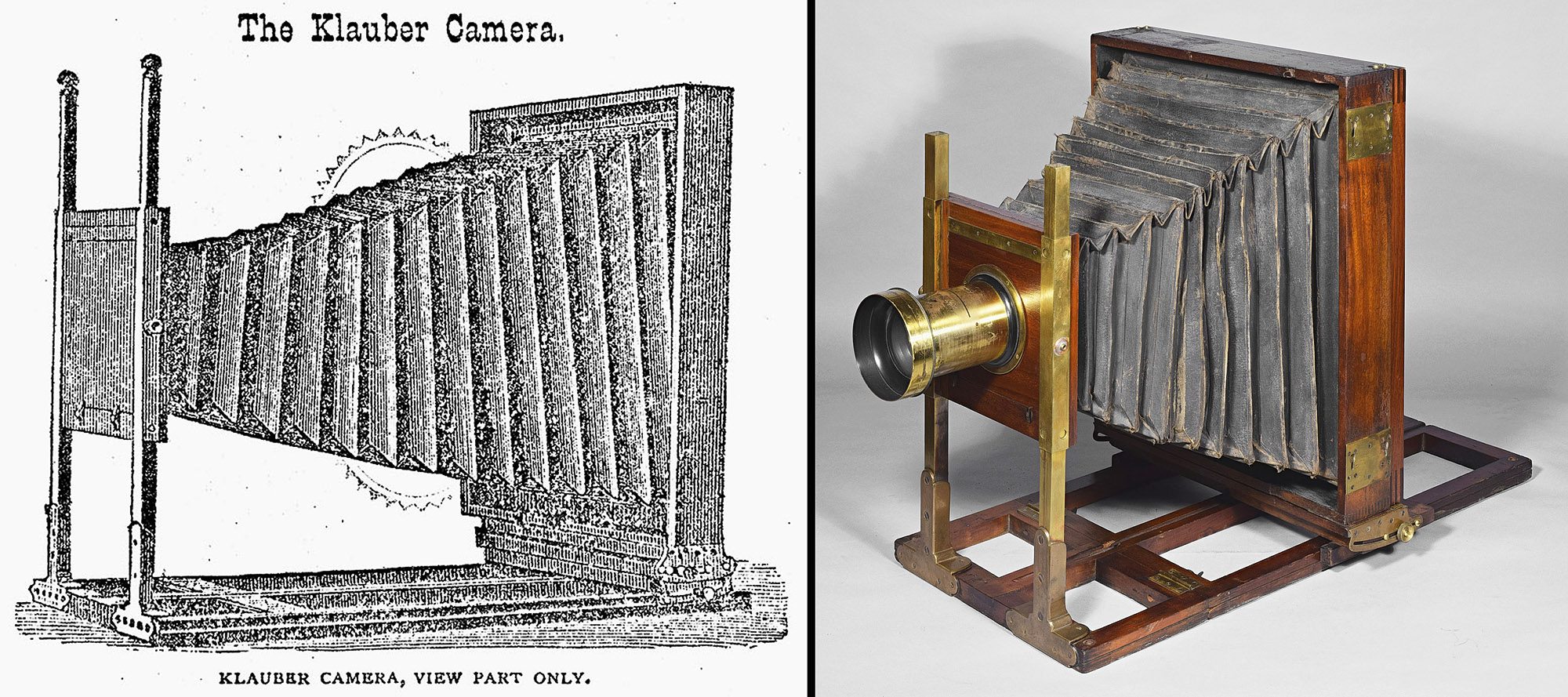
The Klauber Camera, also called the Combination Novel View is an attempt to combine a large studio camera with a field camera. As a studio camera, it is one of the three-standards-type, having a middle standard, which could be used for copying or even enlarging, as well as the usual front and rear standards. In the case of the Klauber Camera, a fourth standard-like wooden support for the bellows was also present. To set up for field work, the bellows would be disengaged from both the middle and rear standards, allowing them to be slid off the rear of the platform. The rear standard would then be slid back on and the bellows re-engaged, leaving only the front and rear standards. A case could be made that the camera example above may be merely a 14x17” Novel View Variation 2.1, but it may be the field version of a Klauber, or perhaps the nearest thing to a Klauber that we will ever see.
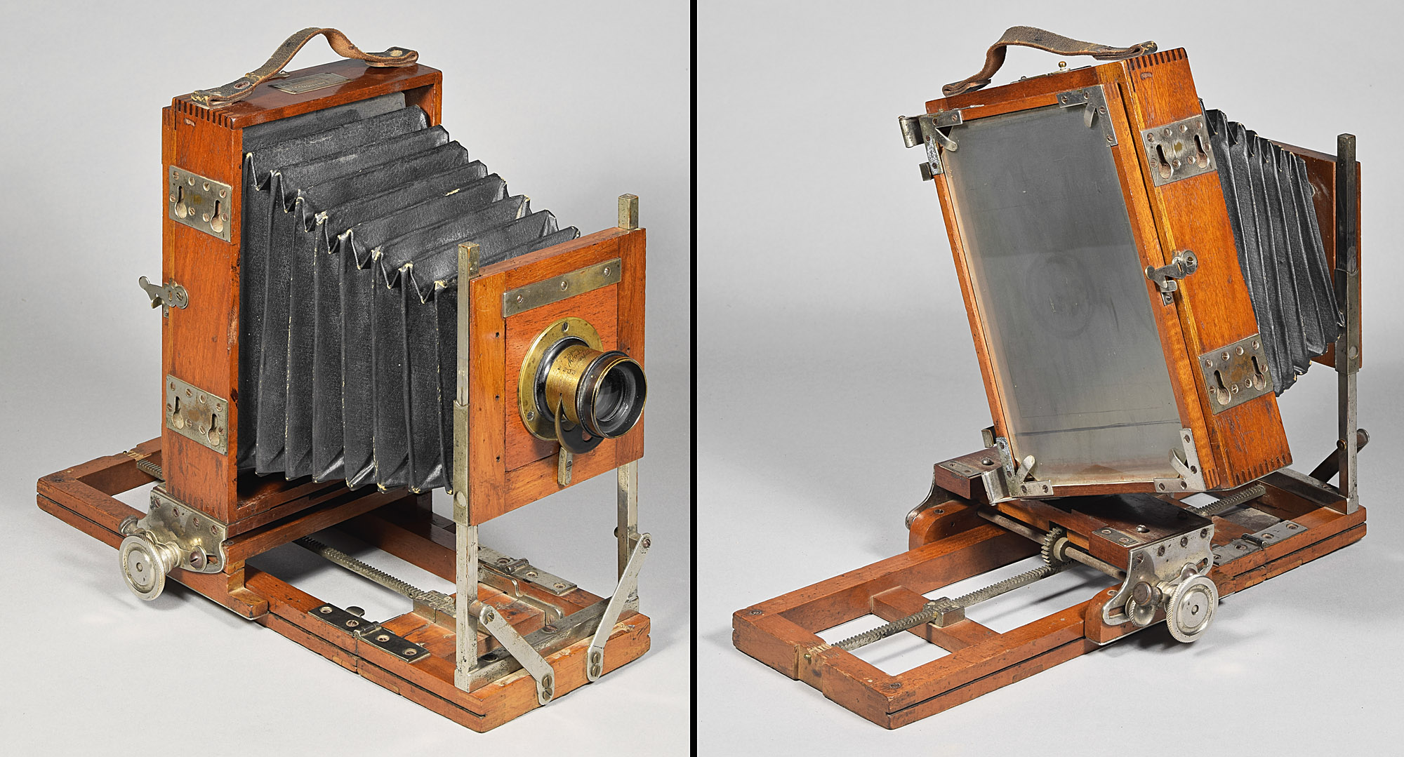
7. a bellows and rear standard that may be rotated together - E. & H.T. Anthony Novelette View Cameras
The Novelette View first appears in print in the September 1886 Anthony catalog, having not been present in the September 1885 catalog. It is a lighter weight version of the Novel View, having a ½” square frame (rather than Novel’s almost twice the size 1”x¾”) for the ground glass and slightly thinner wood in its rear standard.
7.1 Novelette Variation 0.5, LP1211 4x5”, c.1886-c.1897
In the 1886 catalog, the 4x5” Novelette View is described separately from the other sizes of Novelette. This may be because it comes in non-swing version (as the example above) or in single-swing version, whereas other sizes of Novelette have single- or double-swing. Or it may be due to its method of making the bed rigid, consisting of a large brass plate to be slid into the bed joint (one of the best methods of making a bed rigid ever devised). Since it has no central platform rail on which to put the Novel’s combination focus lock thumbscrew and fine focus thumbscrew, its focus lock is a simple thumbscrew screwed into the left side of the movable platform. The bellows rotating and rear standard switching fixtures are the same as in the Novel View and other Novelettes.
7.2 Novelette Variation 1.0 Round Front Stereo, LP079 5x8”, c.1886-c.1897
This Novelette has typical light construction, rotating bellows, rear standard key slots, patent bed hooks, brass corners holding the ground glass. Variation 1.0 Round Front Stereo is distinguished from Variation 1.0 Square Front Non-Stereo by having a wide, stereo-ready lens board (although this example has a single lens instead of two), and a bellows that is appropriately wide in the horizontal mode, and slots inside the camera to fit a stereo septum. The wide lens board has a round or oval front surround that lends its name to the variation.
7.3 Novelette Variation 1.0 Square Front Non-Stereo, LP1238 5x7”, c.1886-c.1897
This variation is identical to the Novelette Variation 1.0 Round Front Stereo, above, except that it has no surround on the front standard, its shape being square, and an appropriately reduced width bellows.
7.4. Novelette Variation 2.0, Solid Platform, LP149 4x5”, c.1885
This example is thought to be earlier than the c.1886 Novelette Variation 0.5 above, primarily because, with its solid plywood bottom and 3+ inch-long thumbscrew, visible from the front, that makes the platform rigid, it harkens back to E.B. Barker’s Feb. 20, 1883 US 272,622 patent (not illustrated here). While it is not used in exactly the same way as in this camera, the patent does have a very long thumbscrew to make the platform rigid. This camera doesn’t have the usual Anthony brass corners for the ground glass frame; instead it has little one screw retainers. Finally, its hardware is nickel-plated brass, more expensive and therefore probably earlier than all brass Novelettes.
7.5 Duplex Novelette View, LP375 5x8” & 8x10”, c.1886-1898
The Duplex Novelette View appeared at approximately the
same time as the other Novelettes, i.e., c.1885-6.
Its round plate that is used in the rotation of the bellows of other
Novelettes is held in
place by sheet brass, one long, curved piece of which can be lifted to
free the bellows from the front standard entirely. This harkens
back to the Novel View Variation 1.5, made before advent of the
rotating bellows front used in most Novels and Novelettes.
Since the rear standard already detaches through the usual key slots,
the Duplex Novelette is unique amongst all Novelettes in
that its bellows and rear standard can be easily removed and replaced
with a different sized rear standard. The
two sizes of rear standards offered were 5x8” and 8x10”, as in the
photographs.
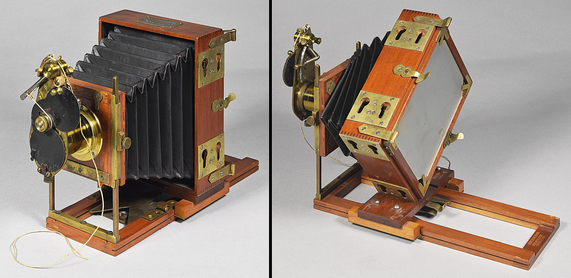
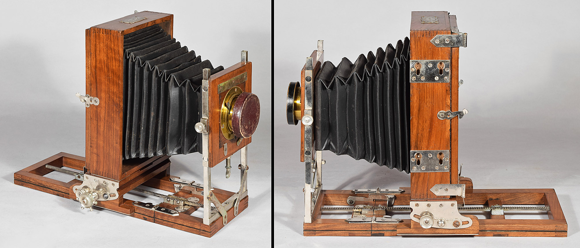
7.6 Front Focus Novelette View, LP904 5x8”, c.1889-c.1897
This Novelette has the usual detachable rear standard and rotating bellows front, but in this case, the platform to accept the rear standard is fixed, and the front standard is provided with a geared track and a geared pinion thumbscrew to focus from the front instead of rear. It was added to the Novelette line around 1889, right around the time the Novel line was dropped.
8. E. & H.T. Anthony Phantom View
8.1 Phantom View, LP144 6½x8½”, Jan. 1888-c.1895
The Phantom View is the most compact folding of all the Anthony rotating bellows cameras. It has key-shaped slots bottom of the front standard as well as key slots in the usual position on the rear movable standard. This allows the front standard to be removed and placed between the rails of the platform. To complete the folding process that makes it so compact, it has a complex long slot on each side at the rear of the fixed platform that allows the rear standard to hinge forward to be parallel to the fixed platform and on top of the already stowed front standard. This results in an extremely compact folding camera, and one that is nearly impossible to remember how to be folded. It was one of the most expensive Anthony cameras and, based on the number seen = 2, not very many were sold.
9. E. & H.T. Anthony Fairy Novel
View
The Fairy Novel View is an early camera; it was introduced in July 1884 in Anthony’s Photographic Bulletin 15, pp. 338-9. It is essentially a Novelette View having a single toothed track running down the middle of its platform, and a matching pinion gear on an axle having a thumbscrew to crank the focus. Since the Fairy Novel predates any of the Novelettes, it would be more correct to say that the Novelette is a Fairy Novel View without the rack and pinion focus.
The Fairy Novel View went through few mechanical modifications during its run. It did, however, have three different styles of its large focusing thumbscrew: 1) round and thin, 2) round and thick, and 3) shaped like the steering wheel of an old ship. It also apparently was made in the square front non-stereo and round front stereo ready type of variations seen in the Novel and Novelette. In that I only ever had three Fairy Novels, each different, and have listed them each as a variation rather than speculating on what more examples should show in the future.
9.1
Fairy Novel View Variation 1.0
Round and Thin Thumbscrew Square Front, LP1223
5x8”, Jul. 1884-c.1889
This variation has the round, thin thumbscrew combined with the square front non-stereo type of bellows and front standard.
9.2 Fairy Novel View Variation 1.1 Round and Thick Thumbscrew Round Front Stereo Ready, LP030 5x8”, Jul. 1884-c.1889
The second of the focus thumbscrew types is a round,
thick version that looks like two of type 1 carved out of one piece of
metal. Being twice as thick, it would provide more traction for
the fingers.
The bellows and front standard are the round front, stereo-ready type.
9.3 Fairy Novel View Variation 2.0 Ship's Wheel Thumbscrew Square Front, Circassian Walnut, LP1004 5x8”, c.1889-c.1898
The obvious difference in this example is that it was constructed of what Anthony calls Circassian Walnut, a wood that is more highly figured and attractive than plain mahogany. This has the third type of thumbscrew that looks like the steering wheel of a ship. Apparently, the increased traction of the type 2 thumbscrew did not provide enough traction. This type showed up in engravings starting in about 1889 and continuing until the model was discontinued. The front standard and bellows are of the square front, non-stereo type.
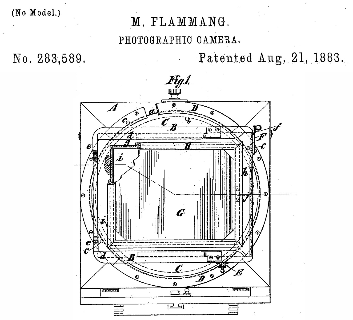
10. a back of the camera can be rotated along a circular brass Inlay – American Optical/Scovill Mfg. Co. Flammang’s Patent Revolving Back View Cameras
As the word "patent" in the names of these cameras indicates, Mathias Flammang patented this revolving back design; one of the drawings of which is below. This design is unusual amongst patented designs in that the design appears to have not changed one bit when translated into a real-life camera. In all variations of the revolving back, the revolving part does not change, down to the spring-loaded pull-out locking mechanism (E in the diagram) or even the tiny brass rod that keeps the plate holder from being removed (F in the diagram).
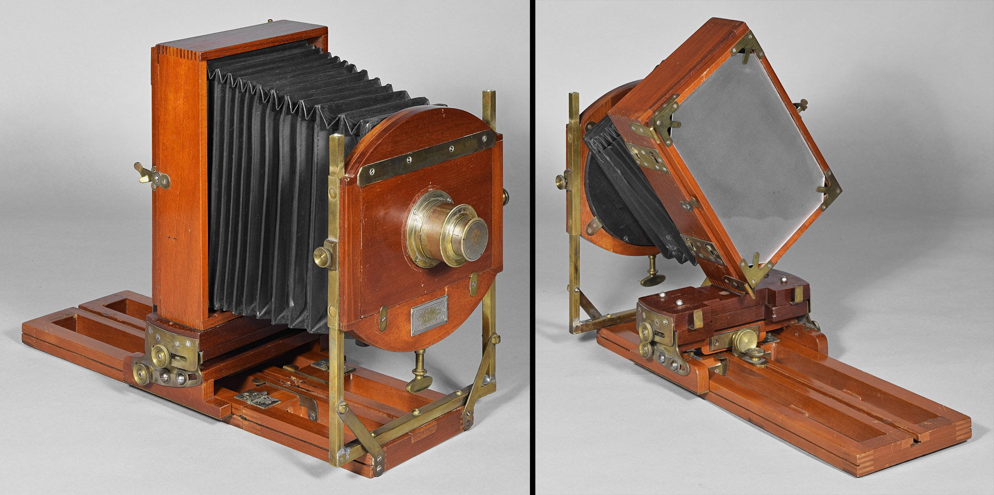
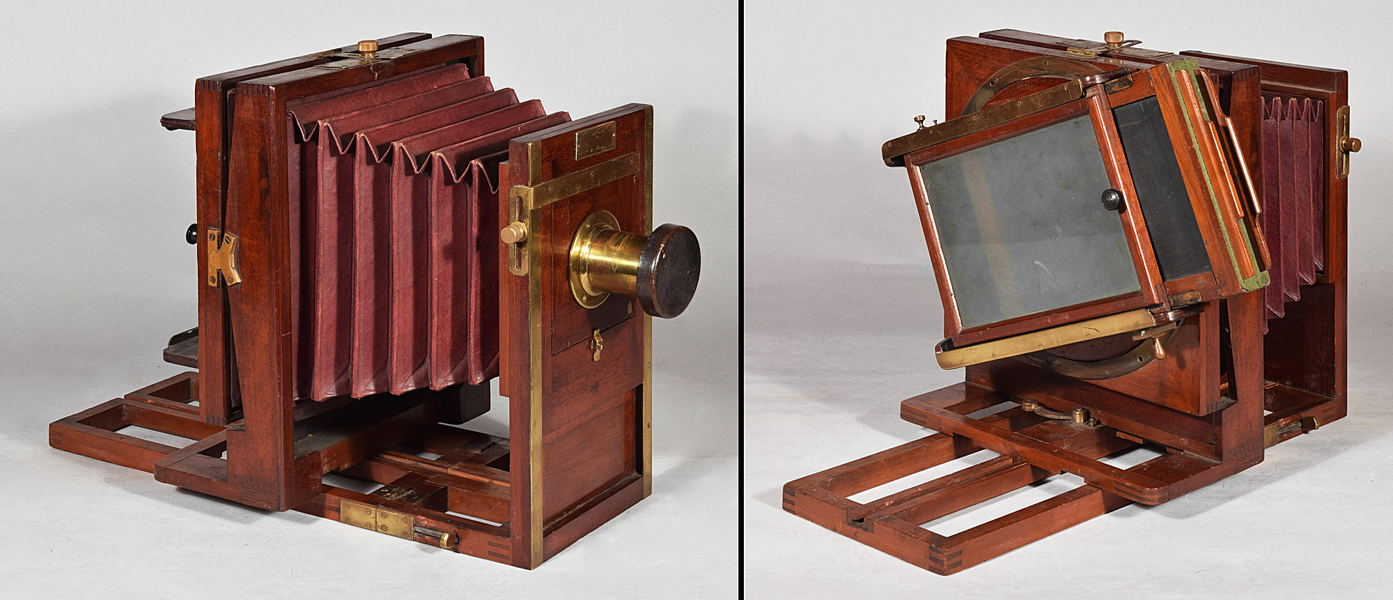
10.1 American Optical Flammang’s Patent Revolving Back Camera – Back Focus Variation 1.0, LP268 11x14”, c.1883
![]()
This variation has its swing pivot at the bottom of the rear standard. I think this is the earliest form of the model. Because the back of the camera encompasses nearly the entire length of the diagonal of the revolving part, Flammang's Patent Revolving Back Cameras are large, thereby defeating the ideal of a light camera. The above 11x14" size is every bit as large as a 14x17" Scovill Acme View (which is the same design except for the back). The revolution lock is visible at the nearest corner of the back. It consists of a spring-loaded ~1/8" diameter brass rod that can catch in any one of four holes, resulting in one of four perpendicular orientations. The remainder of the brass ring is held down by over a dozen wood screws. As per the elegant finishing work of the American Optical Co., 1) for each screw position, screws were installed at random until one was found whose slot is parallel to the edge of the brass ring, 2) each screw was draw-filed, along with its substrate brass ring, in a direction parallel to the edge of the ring until the screws and substrate are even, and 3) the brass is lacquered to protect it from tarnish. Not just the screws on the ring, but all the screws in the camera are treated to the same process; in the left photo above, you can see that the screw slots on the brass strip above the lens board are all perfectly aligned to horizontal.
10.2 American Optical Flammang’s Patent Revolving Back Camera – Back Focus Variation 2.0, LP949 5x7”, c.1886
This variation has its swing pivot in the center of the rear standard. This camera is post-1886, since it has another Flammang patented invention (US 328,664; Oct 20, 1885): a device consisting of a rod (in the photo above: on the right side of the front part of the platform) that can be pushed into a brass cylinder (inside the rear platform) to make the hinged platform rigid,
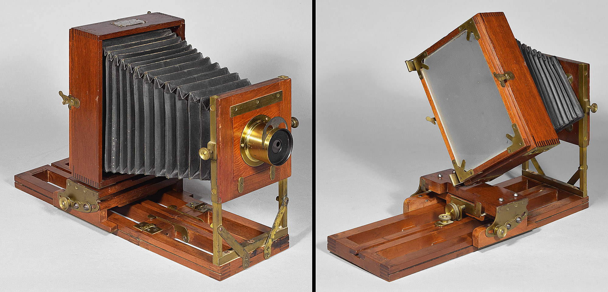
10.3 American Optical Flammang’s Patent Revolving Back Camera – Back Focus Variation 2.2, LP899 6½x8½”, c.1890
Apparently in an attempt to lessen the weight of the camera, this variation has its Flammang ring extending outside the dimensions of the rear standard. This camera also is post-1886, since it has the Flammang rod and cylinder device to make its folding platform rigid.
10.4 American Optical Flammang’s Patent Revolving Back Camera – Back Focus Variation 3.0, LP1196 5x8”, c.1885
Ignoring the fact that this example is a double swing (something available for all Flammang's Revolving Back View variations), this variation is identical to Variation 2 (swing pivot in the middle of the rear standard), except that it has rack and pinion focusing instead of the push-pull focusing that is usual for Flammang Patent cameras. It has a large thumbscrew on the lower right (as viewed from the back) side of the rear standard. The single matching, geared track runs down the middle rail of the frame-like platform. To stabilize the focusing, the side rails of the platform have heavy brass strips on which slide slotted runners on each side of the rear standard. Having seen a counterfeit copy of an American Optical camera with one center rack and pinion track, I can testify that the precise fitting performed by Aamerican Optical is necessary to keep the rear standard perpendicular to the platform rails.
This example is pre-1886, since it does not have the Flammang rod and cylinder device. Instead, this camera has an earlier device that Scovill and many other manufacturers used: a thumbscrew in the platform that can be screwed into the other part of the platform that has a threaded brass plate (visible under the bellows in the right image above).
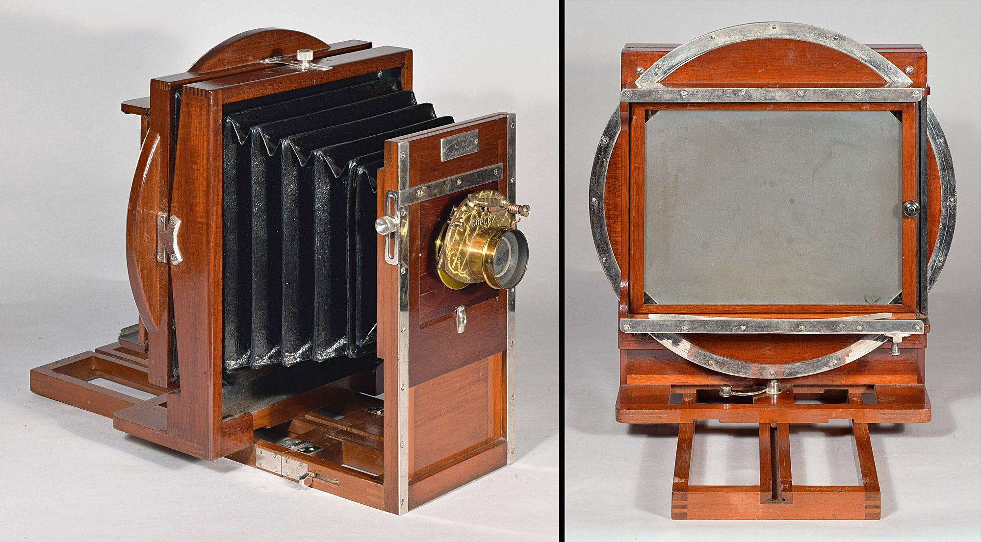
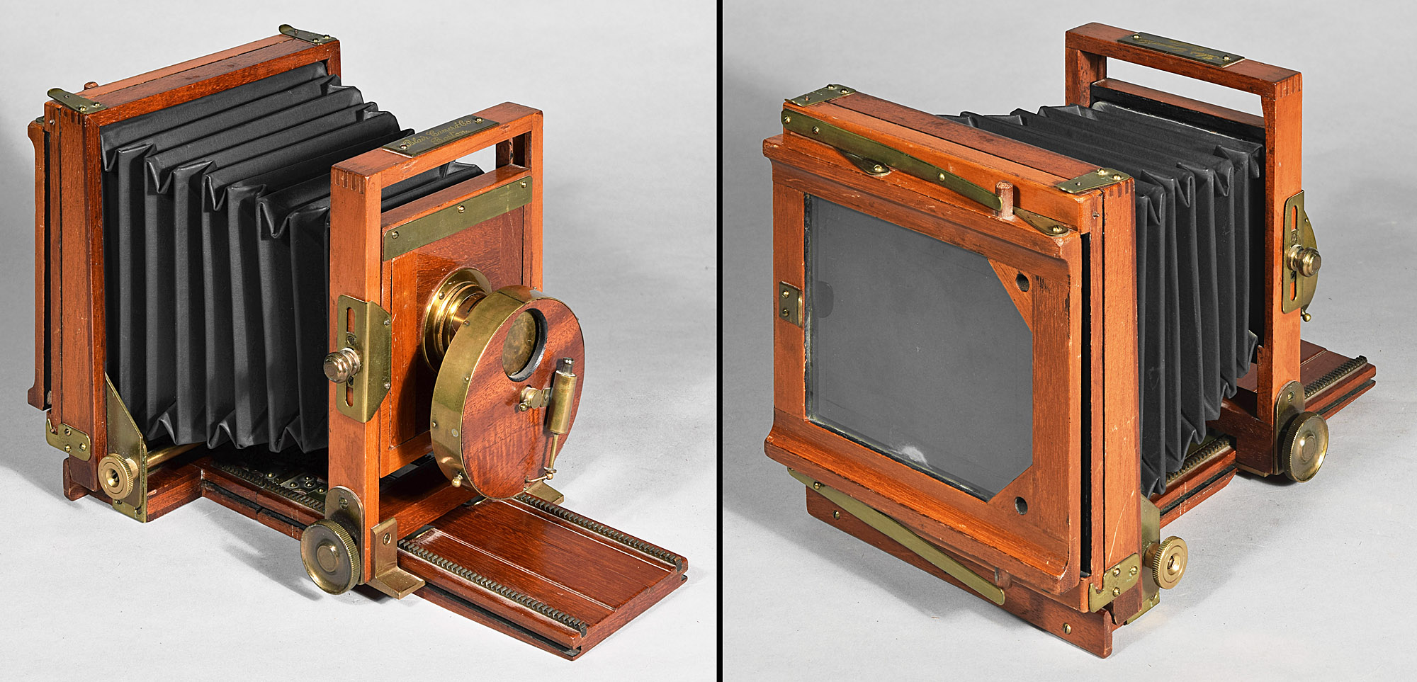
10.5 American Optical Flammang’s Patent Revolving Back Camera – Front Focus Variation 1.0, LP101 5x8”, c.1884-c.1896
This is a front focus version of Flammang's Revolving Back View. It has a rack and pinion focus system identical to that seen in the rear focus revolving camera shown in No. 10.4, except that it extends out onto a hinged front section secured by two of Flammang’s rod and cylinder devices, one on each side. Like the camera No. 10.4, the side rails of the platform have brass strips on which runners stabilize the center focusing.
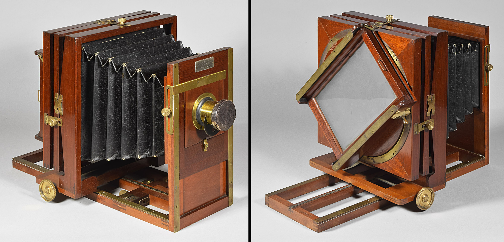
10.6 American Optical Flammang’s Patent Revolving Back Camera – Front Focus Variation 2.0 (Stereo), LP1200 5x8”, c.1890
Although not advertised as available in a stereo version, it apparently could be and was made, as evidenced by the camera shown above. Necessary for stereo is a much wider bellows and front standard, which has extra reinforcement in the form of metal cladding on the lower half of its sides. Immediately above that cladding on each side, there is a brass plate with a threaded hole at its center, the function of which is unknown. Despite the extra width of the front standard, the width of the track below it has not been increased.
10.7 American Optical Elm City (?)View, LP702 6½x8½”, c.1896
This camera is identical to the Flammang’s Patent Revolving Back Camera – Front Focus Variation 1 (No. 10.5), except that its front standard is that of the American Optical Star View (see below), consisting of a simple wooden plank that serves as a movable platform under which is rack and pinion focus using a large thumbscrew and center geared track. Onto this, metal rods support the simply designed lens board and its surround.
The Elm City Camera has not been seen in Scovill catalogs, but was only advertised on the American Annual of Photography and Photographic Times Almanac for 1896 and 1897 "Bargain Pages", under a catagory of cameras called "First quality American Optical's Cameras" (but some are Scovill models rather than American Optical models). This "Bargain Page" seems to be the last reference for a number of models, which implies that 1) Scovill & Adams discontinued a number of models around 1896, and 2) the "Bargain Page" was the outlet for the left-over stock of these discontinued models, as well as over-stocked current models. There are no engravings on the "Bargain Page" to give us a clue as to what the Elm City View looked like.
"Elm City" is a nickname for New Haven, CT, the city in which the Scovill camera factory (the former Samuel Peck factory) was located. In the 1897 Bargain Page, the price of a 6½x8½ Elm City View was $40, compared to that of the Compact View: $25; Leader View: ~$26 (there was no 6½x8½, but 5x8 was $24 and 8x10 was $28); Economic View: $30; Star View: $36; St. Louis View: $40; and Flammang's Revolving Back View: $40. The Elm City View would therefore be similar in finish and complexity of design to the St. Louis View and Flammang's Revolving Back Views. The Elm City View would have to be more complex than the Star View, which itself is pretty complex, given its metal post front standard. The camera shown above meets these criteria, being essentially a Flammang's Revolving Back View with a Star View front standard, and therefore would have been about the same price as them. The last appearance of the Star View was in the 1896 catalog, and the Elm City View may have been replaced it or been discontinued at the same time. Again, this camera may indeed be the Elm City View, but the only evidence is its sale cost related to other models on sale. A photo of the Star View is shown below.
American Optical Star View, LP1082 6½x8½”, c.1896. Note similarity to the above camera.
11. A bellows and back that disengage to be rotated
11.1 Previously discussed E. & H.T. Anthony Novel Variation 1.5, LP1111 5x8”, c.1883
As previously shown and discussed, this early Anthony Novel View has a rear standard that can be disengaged by pushing it to left; then the front standard can be slid up off of its square posts to completely free the top of the camera (right hand image). It is then rotated to the next desired format, the front slid back on the posts, and the rear standard placed on the moveable platform and pushed to the right to secure it.
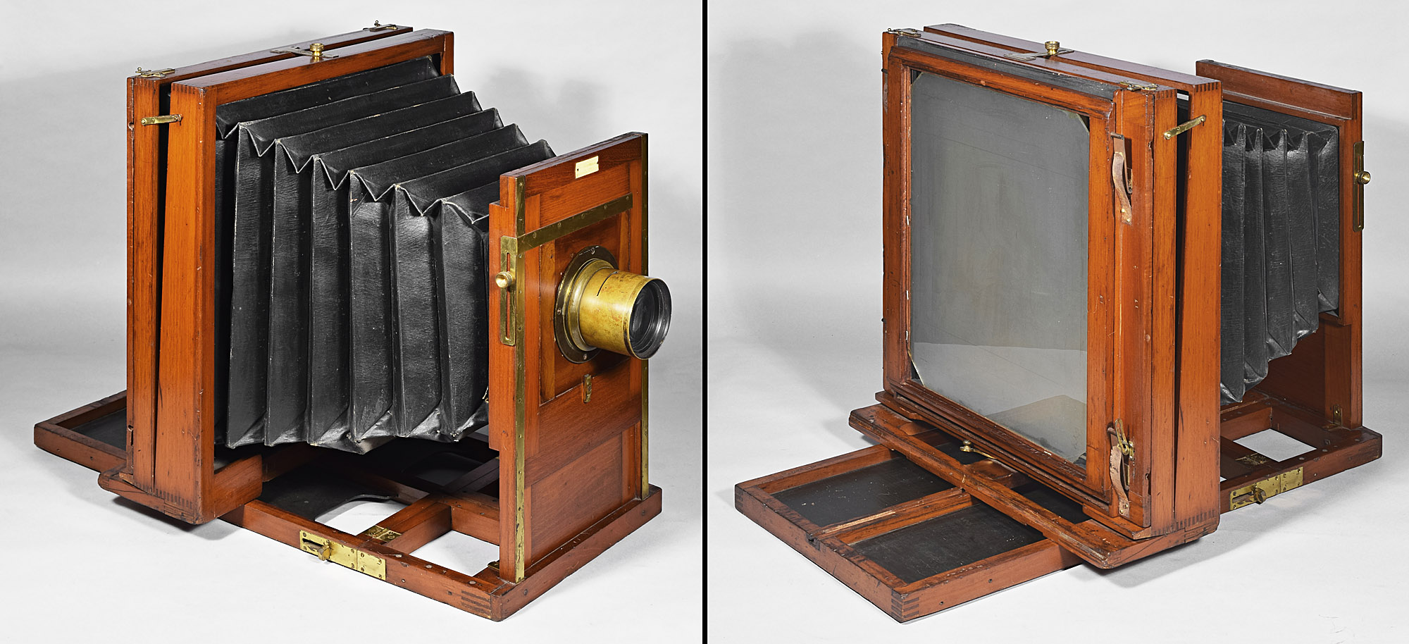
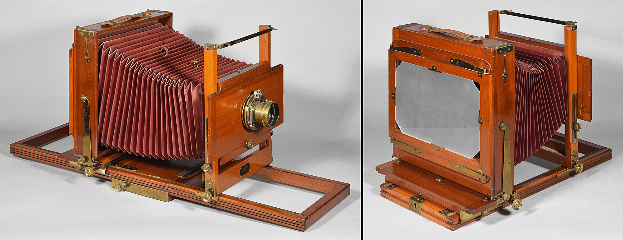
11.2 Flammang Camera Co. Panoramic Camera, LP897 20x36”, c.1899
Mathias Flammang has been mentioned several times above. He was born in 1922 in the Duchy of Luxembourg (according to an obituary in the Bulletin of Photography, although the US census has him born in Belgium and France), came to the United States in 1848, and moved to Newark, NJ in 1869. By 1870, he was a photographer; by 1874 he had moved to a house at 154 Summer Ave., where he lived until his death in 1915. By 1880, he listed himself as a manufacturer of photographic goods. He apparently had an arrangement to assign his many photographic patents to the Scovill Mfg. Co., some of which have been mentioned above (his camera reversing attachment, revolving back camera design, and his rod and cylinder device to make a bed rigid.
There is reference to "an illuminated catalogue (entirely new) of cameras, etc. by the Flammang Camera Co., 180 and 186 West Houston St., New York City." in Wilson's Photographic Magazine, Vol. XXXIII, No. 476, p. 352; August 1896. The company advertised in the 1898 American Annual of Photography & Photographic Times Almanac, ads p.XCIV, which mentions “special cameras”. This would be one of those, having a ground glass size of 20x36”. An interesting part of the camera’s design is that it uses Anthony’s key-shaped slots to anchor the rear standard, and Anthony-type arced slots to provide rear tilt, but uses a design simpler than Anthony’s rotating front disc in that the bellows is lifted out of a slot behind the front standard to be completely free, a method used as far back as 1885 by the Eastman Dry Plate & Film Co. for their Interchangeable View and Eureka View (see No. 12.3), although to disengage the bellows only – not to change from vertical to horizontal formats. Flammang’s revolving bellows could not be used on a camera of this size, unless you wanted one that would be so heavy as to require a squad of servants to handle.
12. a back of the camera un-clips and can be re-clipped at 90⁰ to the first position
This would seem to be about the simplest solution to format change, if you are content with a square camera. It shows up early in the dry plate era, although I wouldn’t be surprised that a removable back was used in the wet plate era, if we only had catalogs with engravings to show us. To change formats, the back is merely unclipped and re-clipped at 90⁰ to the first orientation – simple and inexpensive. It is no surprise that, of all the ways to change from vertical to horizontal, this approach is the one used to the present day.
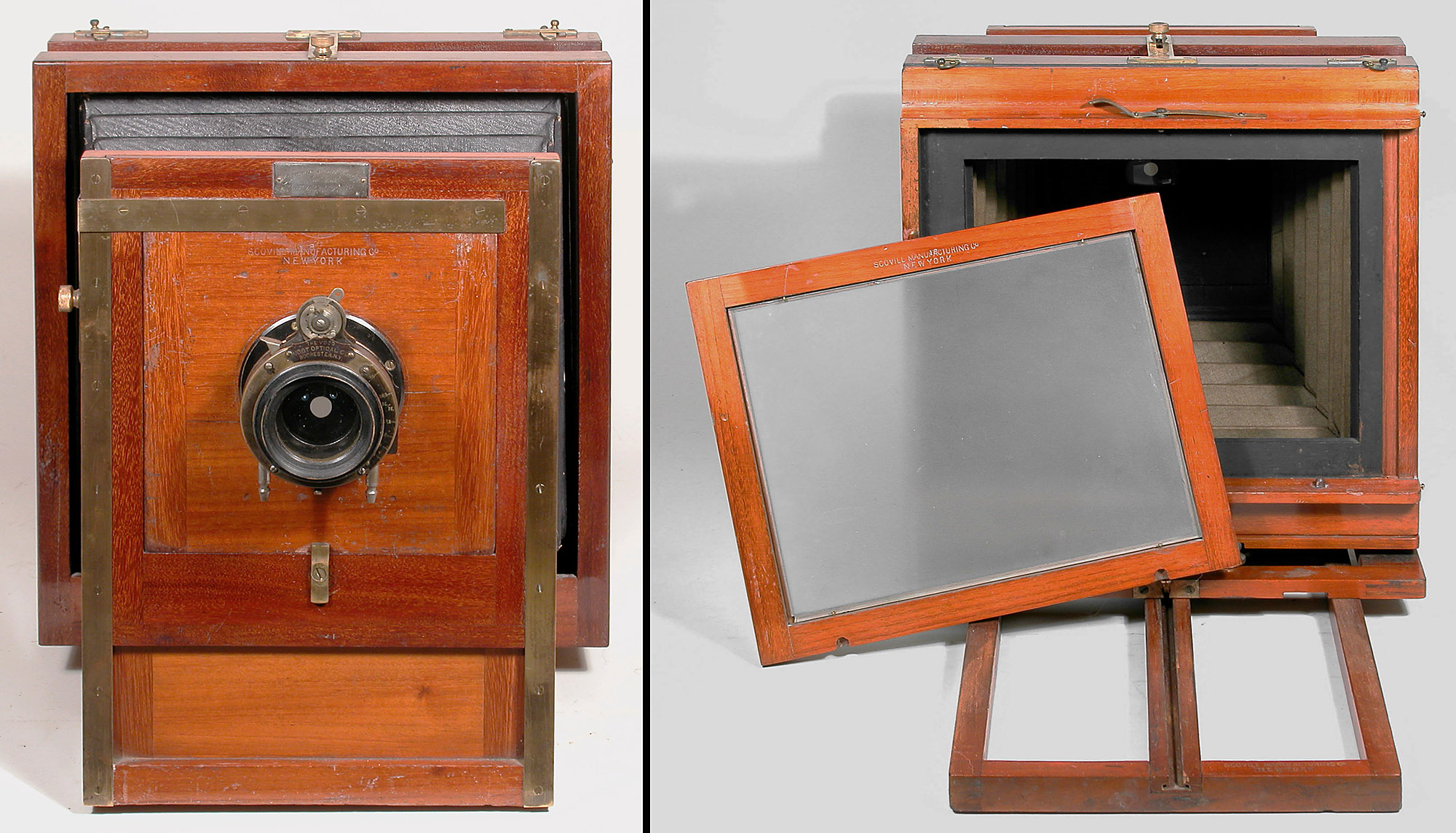
12.1 Scovill Mfg Co. / Scovill & Adams Co. Acme/New Reversible Back View Variation 1.0, LP182 6½x8½”, c.1884-c.1890
The Acme View (the most commonly used of its several names) is similar to and contemporary with American Optical’s top of the line Flammang’s Patent Revolving Back Camera – Back Focus Variation 1, but doesn’t have the revolving (circular brass strip) back. It also has a lesser quality (lighter in color and less figured) mahogany, finished in varnish, not French polished, and plain (not draw filed) brass. Like Flammang’s Back Focus Variation 1.0, this one has the rear standard swing pivot at the bottom. This is the form that the vast majority of Acme Views out there take.
12.2 American Optical/Scovill Mfg. Co. Acme/New Reversible Back View Variation 2.0, LP367 8x10, c.1885
This variation has a different back, in that the same removable back as Variation 1.0, but with an additional removable rectangular section within the removable back, into which a unique plate holder is inserted. Perhaps this was thought to be an improvement over the spring back of Variation 1.0 – it certainly seems lighter in weight, but if you’ve ever come upon an antique camera that is missing a part that has to be removed to insert a plate holder, you do not agree.
12.3 Eastman Dry Plate & Film Co. Eureka View, LP1253 4¼x5½”, c.1885
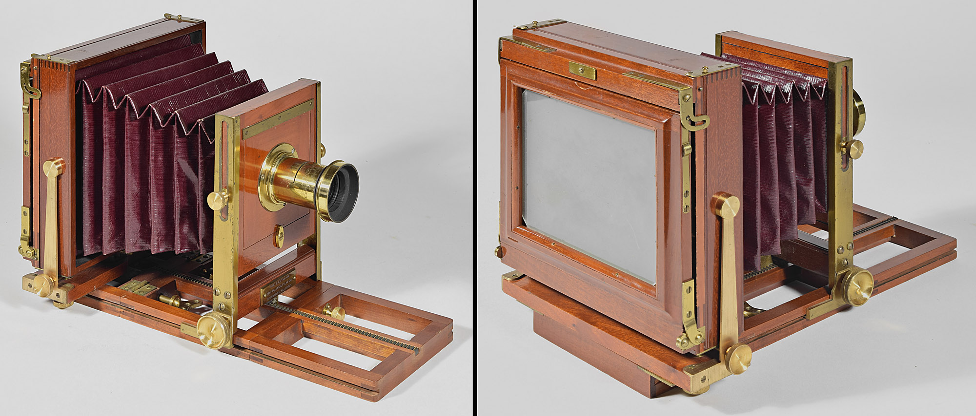
George Eastman made a foray into view cameras before his flexible film took off. The most innovative were the Interchangeable View and the Eureka View, which was an Interchangeable View having a patented Eureka back. The name Eureka never appears in catalogs except as an optional kind of back for the Interchangeable View. The name of Eureka as a model of view camera seems to have only been used in Eastman internal documents, such as production records. The camera is interchangeable because the bellows detaches by turning a small brass tab underneath the front of the bellows, allowing the rear standard and bellows to slide off the rear of the camera. Like the later Duplex Novelette View, the Interchangeable (and Eureka) View had certain size combinations that would fit on the same platform and clip into the front standard. For format change, though, the back would be removed and snapped in at 90⁰.
12.4 Blair Camera Co. Combination Camera Reversible Back Variation 2.6, LP1274 5x7”, c.1884
Thomas Blair and his companies produced a number of view camera models from 1879 through about 1900, along with a bewildering assortment of minor variations that make seem like no two Blair cameras were ever exactly alike. With a few exceptions, all had square, removable, clip-in backs for format choice. The camera below is an example of one of five variations on a model only advertised from c.1884-c.1886.
12.5 Rochester Optical Co. Ideal View Variation 1.0, LP803 8x10”, c.1885
Rochester Optical Co. made a number of view camera models, most of them square with removable backs. The Ideal View was one of their more highly finished and expensive models, and was made in varying forms from c.1885 to c.1897. This variation of the Ideal View is interesting because the back is held on by two rotating cam fasteners on top of the rear standard aided by two plates at the bottom of the rear standard. The rectangular ground glass frame is hinged and also kept in place by identical cam fasteners which can be seen on the right side of the removable back.
12.6 Scovill & Adams Co. Acme/New Reversible Back View Variation 3.0 , LP772 14x17”, c.1890
This later era Acme View has its usual removable back. In this variation, a slim spring back catches and stays open while the plate holder is inserted.
12.7 Blair Camera Co. Cincinnati Improved Reversible Back Variation 3.0, LP160 4x5”, c.1890
Another Blair with many variations, this being one of six (so far), this model has, as a constant, the trapezoidal brass plate at the bottom of the rear standard through which the rear tilt shaft goes. This variation is one of three variations of this model that has a solid wood platform. Its removable back is held in by side plates at the bottom and spring clips at the top. The back also features a brass thumb catch on the left side that allows the photographer to pull the spring-loaded ground glass frame back and to the left to allow easy insertion of the plate holder. This is one of many Blair products to have its ground glass installed in slots cut in the frame; access is provided by the well-fitting left side of the frame, which is held in by two screws.
12.8 G. Gennert Co. Brighton View, LP1177 8x10”, c.1895
The G. Gennert Company competed with Blair, Scovill and Anthony in the 1880’s and 1890’s in manufacturing their own line of high quality view cameras, such as this one. The Brighton View was their top of the line; it was unusual in that it is only one of three view camera models to have both push-pull focus (for the rear standard) and rack and pinion focus (for the front standard). The other models are the E. & H.T. Anthony Clifton View (and the Long Focus Clifton) and the American Optical Ripley View. Some Gennert models like this one have a lens board the installs without hardware, using instead carefully crafted rabbets on the top and bottom edges and a small spring in the front standard that the top of the lens board compresses when installed. The removable back is held by two L-shaped brass parts at the bottom and two spring clips at the top. Its ground glass is held in by the expensive four-sided quarter-round wooden moldings.
12.9 Seneca Camera Mfg. Co. Seneca View Variation 1.0, LP1247 5x7”, c.1910
The Seneca Camera Mfg. Co. was organized in 1895. This is known to be called a Seneca View, from a label on another example. The sheet metal hardware for the rear swing that pivots from the middle is similar to a variation of Seneca Camera City View advertised in Seneca catalogs from 1907 through 1913. The removable back is held by L-shaped parts at the bottom and two combined spring clip and corner guard/reinforcement at the top. This newer camera has its ground glass held in by a angled metal retainer at each corner.
12.10 Conley Camera Co. Model No. 1/Model BS/ Queen/ Seroco View Var. 2.0, LP1045 5x7”, c.1910
Conley uses the same removable back hardware: two supporting L-shaped pieces at the bottom and two combined spring clip and corner guard/reinforcement at the top. The ground glass is held in by a strip of metal at each corner.
12.11 Eastman Kodak Co. Eastman View No. 2, LP1231 7x11”, c.1915
This Kodak view camera has the same setup as the
previous two cameras: the removable back is held at the bottom by two
metal supports, and at the top, it is held by a combination spring clip
and corner reinforcement. The ground glass is held in by four
small pieces of hardware that only require one screw each – less
expensive than the metal strips at each corner that require two screws
each. Oddly, this camera has four springs for the ground glass
frame, a throw-back to previous cameras. Most cameras at this time
had two springs each spanning the width of the back. For that
matter, the successor to this camera, the long running
Kodak View No. 2d
had two springs.