


Construction Details in Field Cameras
A number of interesting details can be found in the myriad models of antique view cameras.
Construction details can be used to help date a camera, as, in general, the more complex (and more expensive to make) is a camera, the earlier it may be. This is universally true within a given model. When introduced, a model is at its most ornate, and usually becomes simpler over time.
Joinery
Daguerreotype and early wet-plate cameras were generally made one at a time in a furniture shop by a craftsman skilled in cabinet making. The wood was joined using a type of joint known as dovetail. An example of dovetail joints is shown to the right, an image of a sliding box type wet plate camera. These joints were hand-sawn, as are most dovetails found in cameras, but they could have also been machine-cut. A dovetail joint is very strong, as the shape of the dovetails holds the joint together more than the glue.
 For
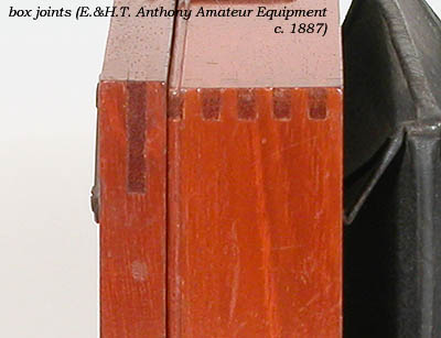
a camera manufactured in a factory, the joints in the
bellows-containing front and rear standards are usually machine-cut box joints.
When making more than one camera, it is worthwhile buying or making the
machinery to cut such box joints. Box joints are fairly strong
because of the large surface area for glue. They are not as strong
as dovetail joints, however.
For
a camera manufactured in a factory, the joints in the
bellows-containing front and rear standards are usually machine-cut box joints.
When making more than one camera, it is worthwhile buying or making the
machinery to cut such box joints. Box joints are fairly strong
because of the large surface area for glue. They are not as strong
as dovetail joints, however.
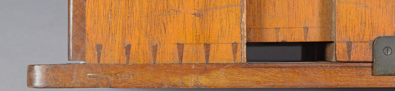
The length of the box-like cut-out is normally the full thickness of the wood, so, in the example to the right, the joint in the ground glass frame is much longer than that in the main box because the wood is wider.
 For
inexpensive cameras, the front and back boxes were the same size, and
fitted onto different sized solid blocks before being attached to the
base. The blocks had to be different sizes to accommodate the
sliding feature of the rear box.
For
inexpensive cameras, the front and back boxes were the same size, and
fitted onto different sized solid blocks before being attached to the
base. The blocks had to be different sizes to accommodate the
sliding feature of the rear box.
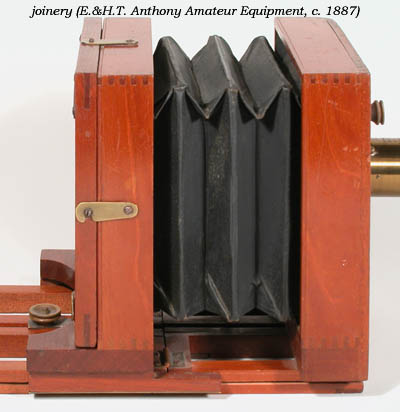
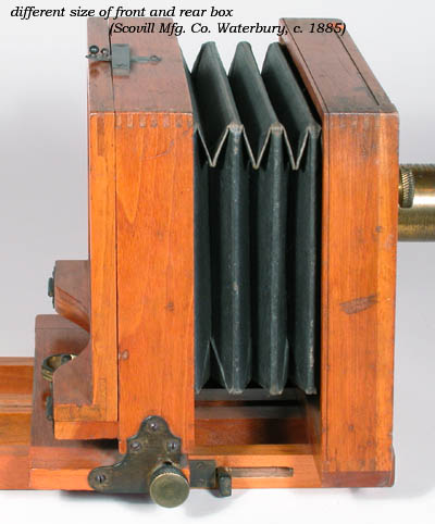 A
slightly more elegant (and more time intensive process) was to produce
uniquely-sized boxes for the front and back standards. In the
example, the brass tilting mechanism bridges the gap between the smaller
box and the sliding base instead of a wooden block.
A
slightly more elegant (and more time intensive process) was to produce
uniquely-sized boxes for the front and back standards. In the
example, the brass tilting mechanism bridges the gap between the smaller
box and the sliding base instead of a wooden block.
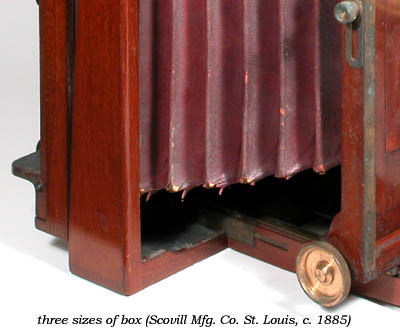 More
complex, expensive models were made having a different sized box (and
therefore a separate production operation) for each camera part.
More
complex, expensive models were made having a different sized box (and
therefore a separate production operation) for each camera part.
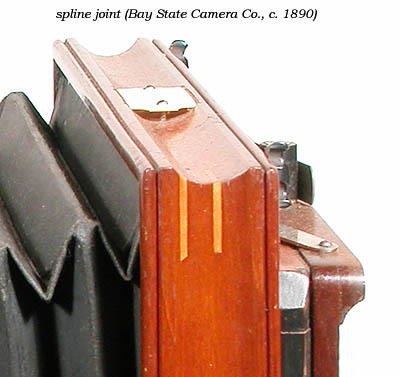
Spline joints (joints reinforced by thin strips of wood) were occasionally used, as in this magnificent example of craftsmanship from the Bay State Camera Co.
Attaching the Ground Glass
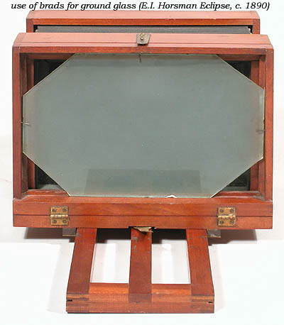 The
most cost-effective manner of keeping a sheet of glass in a frame is by
the judicious insertion of four brads. This was used, naturally on
the least expensive cameras and relatively early cameras.
The
most cost-effective manner of keeping a sheet of glass in a frame is by
the judicious insertion of four brads. This was used, naturally on
the least expensive cameras and relatively early cameras.
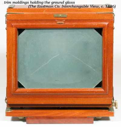 Expensive
early cameras possessed elegant applied trim moldings to hold the ground
glass. Replacing a broken ground glass in one of these is a major
operation. The moldings on the example to the right are a little over
1/8" thick and held in place by tiny brads.
Expensive
early cameras possessed elegant applied trim moldings to hold the ground
glass. Replacing a broken ground glass in one of these is a major
operation. The moldings on the example to the right are a little over
1/8" thick and held in place by tiny brads.
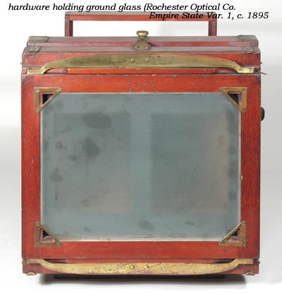
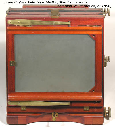 The
Blair Camera Co., ever the design rebels, had their own way of
installing a ground glass. From the earliest Blair cameras, the
ground glass has been slid into narrow grooves cut into the frame.
The left hand side of the frame is removable and held by screws should
the need arise to replace the glass. This creates the illusion
that nothing is holding the glass. From about 1890 on, most camera
backs of Blair origin sport the two triangular pieces of wood, each with
a hole. The purpose or use of these is not obvious. Cameras
build prior to 1890 seem to have gotten along without them. Blair
also included the brass pull seen on the left side of the ground glass
frame. Push this to the left, and the frame pulls back and left to
facilitate loading the plate holder.
The
Blair Camera Co., ever the design rebels, had their own way of
installing a ground glass. From the earliest Blair cameras, the
ground glass has been slid into narrow grooves cut into the frame.
The left hand side of the frame is removable and held by screws should
the need arise to replace the glass. This creates the illusion
that nothing is holding the glass. From about 1890 on, most camera
backs of Blair origin sport the two triangular pieces of wood, each with
a hole. The purpose or use of these is not obvious. Cameras
build prior to 1890 seem to have gotten along without them. Blair
also included the brass pull seen on the left side of the ground glass
frame. Push this to the left, and the frame pulls back and left to
facilitate loading the plate holder.
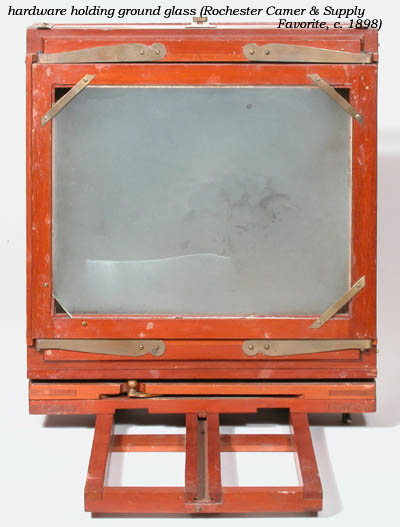
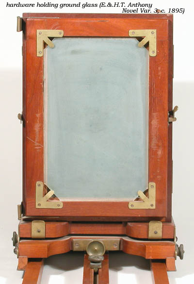 Most
manufacturers found it economical to use brass hardware pieces to hold
the ground glass. Examples include a common E.&H.T. Anthony type
and two common Rochester Optical types.
Most
manufacturers found it economical to use brass hardware pieces to hold
the ground glass. Examples include a common E.&H.T. Anthony type
and two common Rochester Optical types.
.
Bases/Beds/Rails
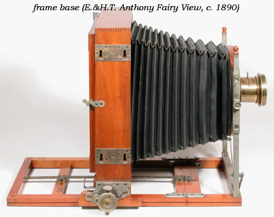 The
vast majority of view cameras were designed to have a frame of wood as
the base(s) of the camera. This saves weight, as air is lighter
than wood.
The
vast majority of view cameras were designed to have a frame of wood as
the base(s) of the camera. This saves weight, as air is lighter
than wood.
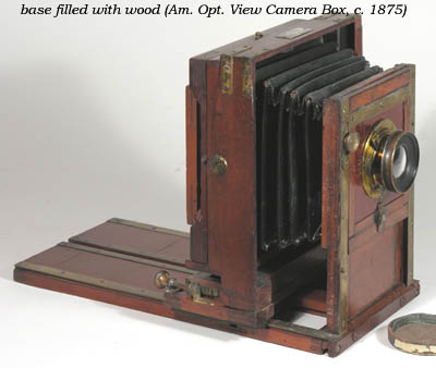 However,
early cameras often had the rails filled in with wood, probably to make
the assembly more rigid.
However,
early cameras often had the rails filled in with wood, probably to make
the assembly more rigid.
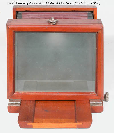 The
earliest Rochester Optical Co. New Models had a unique beveled-edge rail
strengthened by a substantially-thick wood fill. It was used in
all sizes of New Models of the era, and is documented in catalogs of the
time.
The
earliest Rochester Optical Co. New Models had a unique beveled-edge rail
strengthened by a substantially-thick wood fill. It was used in
all sizes of New Models of the era, and is documented in catalogs of the
time.
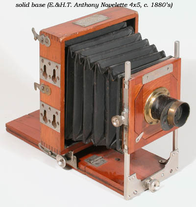 Other
manufacturers seem to have used solid bases on smaller cameras, perhaps
for convenience - surely these little guys did not need extra strength.
Other
manufacturers seem to have used solid bases on smaller cameras, perhaps
for convenience - surely these little guys did not need extra strength.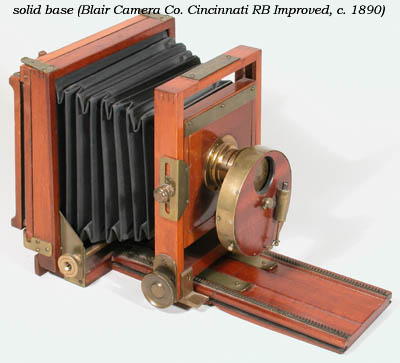
Bellows
 Although
some of the first cameras used box-in-a-box focusing, all the view
cameras in the late wet plate and the dry plate eras used bellows to
allow the camera to remain light tight during focus movements. Bellows
are constructed of flexible materials which vary with the cost of the
camera and the time period of manufacture.
Although
some of the first cameras used box-in-a-box focusing, all the view
cameras in the late wet plate and the dry plate eras used bellows to
allow the camera to remain light tight during focus movements. Bellows
are constructed of flexible materials which vary with the cost of the
camera and the time period of manufacture.
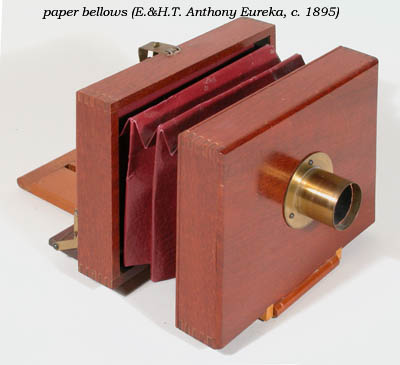
The very least expensive cameras - those given away to boys as prizes for selling subscriptions were made of a single layer of folded stiff paper.
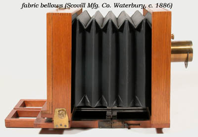 Other
than these really cheap models, view cameras generally had bellows
constructed of an inner layer of black cloth, stiffeners cut from stiff
cardboard (or wood slats for very large bellows) and an outer layer.
The stiffeners are fit and are installed along every flat part of the
bellows - there may be dozens of stiffeners per bellows. The inner
and outer layers were glued to the stiffeners to produce the
assembly.
Other
than these really cheap models, view cameras generally had bellows
constructed of an inner layer of black cloth, stiffeners cut from stiff
cardboard (or wood slats for very large bellows) and an outer layer.
The stiffeners are fit and are installed along every flat part of the
bellows - there may be dozens of stiffeners per bellows. The inner
and outer layers were glued to the stiffeners to produce the
assembly.
The common or pedestrian cameras of the 19th century had outer layers of rubberized cloth. They are usually black (although Rochester Optical liked brown in some New Models), and can be recognized easily from the cloth surface texture. This was a robust material, and may of these 120-year-old cameras are as light-tight today as they were when they were manufactured. Others only need a touch-up in the corners to be light-tight.
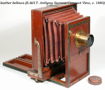 The
most expensive material to use as an outer bellows layer was very thin
red or maroon leather, sometimes called Russian leather.
Unfortunately for these otherwise finely crafted cameras, leather does
not stand the test of time as well as rubber and cloth, so many leather
bellows are in tatters. The example at the right was actually very
artfully posed with the assistance of a paper clip so as to make the
bellows appear more together than they really are.
The
most expensive material to use as an outer bellows layer was very thin
red or maroon leather, sometimes called Russian leather.
Unfortunately for these otherwise finely crafted cameras, leather does
not stand the test of time as well as rubber and cloth, so many leather
bellows are in tatters. The example at the right was actually very
artfully posed with the assistance of a paper clip so as to make the
bellows appear more together than they really are.
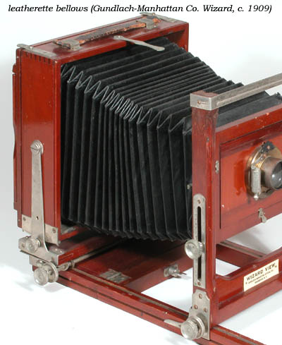 Approximately
1910, leatherette (plastic-coated cloth embossed with a
pebble-grain to look like leather) began to replace other outer layers
in bellows. It was as robust as rubberized cloth, and could have
the red or maroon look of leather. About the same time, it was
found that bellows would be more serviceable if the corners were not
pointed, but rather folded to make an octagon cross-section, as shown in
the example at right.
Approximately
1910, leatherette (plastic-coated cloth embossed with a
pebble-grain to look like leather) began to replace other outer layers
in bellows. It was as robust as rubberized cloth, and could have
the red or maroon look of leather. About the same time, it was
found that bellows would be more serviceable if the corners were not
pointed, but rather folded to make an octagon cross-section, as shown in
the example at right.
Stereo
The 1860's through 1900 was the time of stereo. There was no radio, television or cinema for entertainment, and every parlor had its stereoscope and pile of stereocards of romantic-looking scenery around the world. When traveling, people often bought souvenir stereocards to be viewed at home. While it was mainly the professional who produced stereo photos, and they generally used cameras designed strictly for stereo, amateurs could hope, and many amateur cameras in the 1880's and 1890's that were mainly non-stereo could be adapted for stereo.
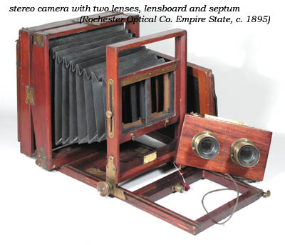 Stereo
requires specific adaptations of the view camera, not the least of which
was usually two lenses, spaced apart about the same distance as human
eyes for the most natural-looking photos (sometimes hyper-stereos were
taken with much larger distances). The camera must have a lens
board wide enough to accommodate two lenses, as the Empire State to the
right. It might also have a stereo shutter, like the box-like
Thornton-Picard "mouse-trap" shutter in the example. There also
must be effective separation of the light beams from each lens,
accomplished by a septum, which in this case is constructed like
a bellows, and can just be seen behind the hole where the lens board
would go.
Stereo
requires specific adaptations of the view camera, not the least of which
was usually two lenses, spaced apart about the same distance as human
eyes for the most natural-looking photos (sometimes hyper-stereos were
taken with much larger distances). The camera must have a lens
board wide enough to accommodate two lenses, as the Empire State to the
right. It might also have a stereo shutter, like the box-like
Thornton-Picard "mouse-trap" shutter in the example. There also
must be effective separation of the light beams from each lens,
accomplished by a septum, which in this case is constructed like
a bellows, and can just be seen behind the hole where the lens board
would go.
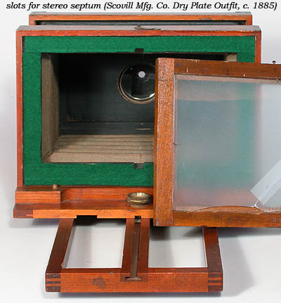 A
camera that could be adapted for stereo (even though it may have never
been used that way) usually is the 5x8" size, which would produce two
4x5 negatives that could easily be trimmed to produce a standard 3.5x7"
stereocard. Such a camera can be recognized by two slots in the
back, where the septum would fit.
A
camera that could be adapted for stereo (even though it may have never
been used that way) usually is the 5x8" size, which would produce two
4x5 negatives that could easily be trimmed to produce a standard 3.5x7"
stereocard. Such a camera can be recognized by two slots in the
back, where the septum would fit.
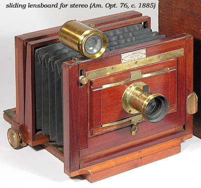 Sliding
lens boards were made for those people that didn't mind using one lens
to expose half of the negative, then sliding the lens over and exposing
the second half of the negative at a slightly later time.
Occasionally, such stereo photos can be seen on stereocards, featuring a
ghostly person or animal who appears in quite different places on the
two images.
Sliding
lens boards were made for those people that didn't mind using one lens
to expose half of the negative, then sliding the lens over and exposing
the second half of the negative at a slightly later time.
Occasionally, such stereo photos can be seen on stereocards, featuring a
ghostly person or animal who appears in quite different places on the
two images.
By about 1920, amateurs no longer craved cameras the could take stereo photos, and the wide lens board cameras were dropped by manufacturers.